background image

3

Install the GPU card

4

Install the system cover

5

Follow the procedure listed in 

After working inside your system

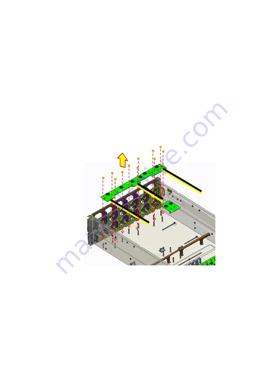
Removing a GPU power interposer board

Prerequisites

1

Follow the safety guidelines listed in 

Safety instructions

.

2

Follow the procedure listed in 

Before working inside your system

.

3

Remove the system cover.

4

Remove the GPU card

.

5

Remove the GPU support bracket.

6

Remove the PCIe switch board module.

Steps

Remove the eleven screws securing the GPU power interposer board.

Lift the GPU power interposer board from the system.

Figure 36. Removing the GPU power interposer board

Next steps

Disconnect all the cables from the GPU power interposer board. For more information, see 

Power cable assembly to PDB

Installing a GPU power interposer board

Installing and removing system components

61

Summary of Contents for DSS8440

Page 1: ...Dell EMC DSS8440 Installation and Service Manual Regulatory Model B21S Series Regulatory Type B21S001 ...

Page 2: ...amage to hardware or loss of data and tells you how to avoid the problem WARNING A WARNING indicates a potential for property damage personal injury or death 2019 Dell Inc or its subsidiaries All rights reserved Dell EMC and other trademarks are trademarks of Dell Inc or its subsidiaries Other trademarks may be trademarks of their respective owners 2019 04 Rev A00 ...

Page 3: ...14 USB ports specifications 14 COM port specifications 14 VGA port specifications 15 LOM port specifications 15 Environmental specifications 15 System diagnostics and indicator codes 15 NIC indicator codes 16 Power supply unit indicator codes 17 4 Initial system setup and configuration 19 Setting up your system 19 iDRAC configuration 19 Options to set up iDRAC IP address 19 Log in to iDRAC 19 5 Pr...

Page 4: ...carrier and drive 48 Installing the drive and drive carrier 49 Drive backplane 50 Removing the drive backplane 50 Installing the drive backplane 51 Power supply unit 52 Removing a power supply unit 52 Installing a power supply unit 53 Expansion cards and expansion card risers 53 Removing a GPU 53 Installing a GPU 54 Removing a GPU support bracket 55 Installing a GPU support bracket 56 Removing the...

Page 5: ...Replacing the backup battery 82 Power distribution board 83 Removing the power distribution board 83 Installing the power distribution board 84 PSB power interposer board 85 Removing the PSB power interposer board 85 Installing the PSB power interposer board 86 Front control module 87 Removing the front control module 87 Installing the right control panel 87 Fan louvers 88 Removing the fan louvers...

Page 6: ... PDB assembly to PDB 120 IDC cable Riser 2 PDB assembly to riser board 2 121 Mini SAS HD cable assembly PERC HDBP 122 Mini SAS HD cable assembly HDBP MB 123 Power cable BP PDB assembly to BP 123 Power cable BP PDB assembly to PDB 124 Power cable assembly to PDB 125 Power cable assembly to PIB 133 Power cable1 assembly to Riser1 133 Power cable2 Riser PDB assembly to PDB 135 Power cable2 Riser PDB ...

Page 7: ...ocument provides an overview about the system information on installing and replacing components technical specifications diagnostic tools and guidelines to be followed while installing certain components 1 About this document 7 ...

Page 8: ...C DSS8440 system The chapter includes figures of the products a list of the server system features and diagrams showing the location of the components and connections on the server systems Figure 1 Dell EMC DSS8440 front View Figure 2 Dell EMC DSS8440 rear view 2 8 Dell EMC DSS8440 system overview ...

Page 9: ...e 14G leveraged PowerEdge C4140 The system contains configuration A with 8x 10x double width GPGPU 10x 2 5 hot swap storage drives no expander single or dual Skylake processors 845 4mm maximum length PCIe slots through PCIe Switch Board PSB and C4140 risers 24x DIMM slots quad hot plug power supply units rNDC and the ability to use an HBA for the data drives Figure 3 DSS8440 system feature overvie...

Page 10: ...r on indicator power button 2 System health indicator 3 System identification button Rear view of the system Figure 5 Rear view of the system 1 Slots 4 5 14 15 2 Slots 19 16 3 Drive 0 9 4 Slot 1 5 Slot 3 6 ID 7 Power Jack 8 RJ45 9 DB9 10 DB15 11 2x USB 3 0 12 2x RJ45 2xSFP 13 Power Supply 1 to 4 10 Dell EMC DSS8440 system overview ...

Page 11: ...nsions Chassis weight Processor specifications PSU specifications Cooling fans specifications System battery specifications Expansion card riser specifications Memory specifications Drive specifications Ports and connectors specifications Environmental specifications System diagnostics and indicator codes 3 Technical specifications 11 ...

Page 12: ...hes With bezel 870 mm 34 25 inches 830 mm 32 67 inches 845 mm 33 26 inches Chassis weight Table 2 Chassis weight System Maximum weight with all drives DSS8440 2 CPU 10 GPU 10 HDD 1 H730P 1 CX5 46 3 Kg 102 07 lb Processor specifications TheDell EMC DSS8440 system supports two Intel Xeon Scalable processors with up to 20 cores per processor 12 Technical specifications ...

Page 13: ...0W Frequency 50 60 Hz Efficiency VIN 230Vac 89 10 load 93 20 load 94 50 load 100 load 91 5 load Power Factor PF at 230Vac 50 60 Hz 0 88 10 load 0 94 20 load 0 98 50 load 0 99 100 load iTHD 230Vac 60 Hz 25 0 load 25 10 load 10 20 load 5 50 load 4 100 load Hold up Time 13 5ms 100 load Conducted EMI Class A Radiated EMI Class A Output Main DC Output Voltage Regulation 12 2V 5 Output current 196 72A h...

Page 14: ...MM Dual rank 16 GB 32 GB 384 GB RDIMM Single rank 8 GB 16 GB 192 GB NOTE Ensure that all the memory slots are populated either with DIMMs or DIMM blanks NOTE It is recommended to have all DIMMs of the same type Drive specifications The Dell EMC DSS8440 system supports 10 x 2 5 inch hard drives with following configurations Drive 0 1 Support SATA SAS only Drive 2 7 Support SATA SAS NVMe only Drive ...

Page 15: ...ed by 1 C 300m 1 F 547ft above 950 m 3117 ft One rotor fan failure 10 C 35 C Maximum temperature is reduced by 1 C 300m 1 F 547ft above 950 m 3117 ft Non Operation 40 C to 65 C Table 6 Humidity Humidity Operation 10 to 80 RH non condensing Non Operation 5 to 95 RH non condensing Table 7 Maximum Altitude Maximum Altitude Operation 10 000 ft Non Operation 30 000 ft System diagnostics and indicator c...

Page 16: ...en or no video output See the Getting help section System identification button The identification button on the front and back panels can be used to locate a particular system within a rack When one of these buttons is pressed the corresponding system identification button on the back flashes until one of the buttons is pressed again Press the system identification button to turn the system ID on...

Page 17: ...AC power supply units PSUs have an illuminated translucent handle that serves as an indicator The indicator shows whether power is present or a power fault has occurred Figure 8 AC PSU status indicator 1 AC PSU status indicator handle Table 10 AC PSU status indicators Convention Power indicator pattern Condition A Green A valid power source is connected to the PSU and the PSU is operational B Flas...

Page 18: ...ilure to turn the system on CAUTION When correcting a PSU mismatch replace only PSU with the blinking indicator Swapping the PSU to make matched pair can result in an error condition and unexpected system shutdown To change from a high output configuration to a low output configuration or vice versa you must turn off the system CAUTION The 120 V AC PSU is not recommended for this system Operating ...

Page 19: ... IP address You must configure the initial network settings based on your network infrastructure to enable the communication to and from iDRAC You must use the default iDRAC IP address 192 168 0 120 to configure the initial network settings including setting up DHCP or a static IP for iDRAC You can set up the IP address by using one of the following interfaces NOTE To access iDRAC ensure that you ...

Page 20: ...o view the help text in the text browser press F1 You can access system setup by using two methods Standard graphical browser The browser is enabled by default Text browser The browser is enabled by using Console Redirection Viewing System Setup To view the System Setup screen perform the following steps 1 Turn on or restart your system 2 Press F2 immediately after you see the following message F2...

Page 21: ...mation Provides information about the system such as the system model name BIOS version and Service Tag Memory Settings Provides information and options related to the installed memory Processor Settings Provides information and options related to the processor such as speed and cache size SATA Settings Provides options to enable or disable the integrated SATA controller and ports NVMe Settings Pr...

Page 22: ...you see the following message F2 System Setup NOTE If your operating system begins to load before you press F2 wait for the system to finish booting and then restart your system and try again 3 On the System Setup Main Menu screen click System BIOS 4 On the System BIOS screen click System Information System Information details The System Information screen details are explained as follows Option D...

Page 23: ...iption Installed Memory Size Specifies the amount of DDR4 memory installed in the system System Memory Size Specifies the memory size in the system System Memory Type Specifies the type of memory installed in the system System Memory Speed Specifies the system memory speed System Memory Voltage Specifies the system memory voltage Video Memory Specifies the amount of video memory System Memory Test...

Page 24: ...or Settings screen perform the following steps 1 Power on or restart your system 2 Press F2 immediately after you see the following message F2 System Setup NOTE If your operating system begins to load before you press F2 wait for the system to finish booting and then restart your system and try again 3 On the System Setup Main Menu screen click System BIOS 4 On the System BIOS screen click Process...

Page 25: ...be enabled if the operating system supports it It is set to Disabled by default Configurable TDP Enables you to configure the TDP level The available options are Nominal Level 1 and Level 2 This option is set to Nominal by default NOTE This option is only available on certain stock keeping units SKUs of the processors SST Performance Profile Enables you to reconfigure the processor using Speed Sel...

Page 26: ...d to the embedded SATA drives during POST This option is applicable only for AHCI mode This option is set to Enabled by default Write Cache Enables or disables the command for the embedded SATA drives during POST This option is set to Disabled by default Port n Enables you to set the drive type of the selected device For AHCI Mode or RAID Mode BIOS support is always enabled Option Description Mode...

Page 27: ... mode it replaces the system BIOS 1 From the System Setup Main Menu click Boot Settings and select Boot Mode 2 Select the UEFI boot mode you want the system to boot into CAUTION Switching the boot mode may prevent the system from booting if the operating system is not installed in the same boot mode 3 After the system boots in the specified boot mode proceed to install your operating system from t...

Page 28: ...k System BIOS 4 On the System BIOS screen click Network Settings Network Settings screen details The Network Settings screen details are explained as follows Option Description UEFI PXE Settings Enables or disables the device When enabled a UEFI PXE boot option is created for the device UEFI HTTP Settings Enables or disables the device When enabled a UEFI HTTP boot option is created for the device...

Page 29: ...ls are explained as follows Option Description iSCSI Initiator Name Specifies the name of the iSCSI initiator iqn format iSCSI Device1 Enables or disables the iSCSI device When enabled a UEFI boot option is created for the iSCSI device automatically iSCSI Device1 Settings Enables you to control the configuration of the iSCSI device Integrated Devices You can use the Integrated Devices screen to vi...

Page 30: ... support the feature Embedded Video Controller Enables or disables the use of Embedded Video Controller as the primary display When set to Enabled the Embedded Video Controller is used as the primary display even if add in graphic cards are installed When set to Disabled an add in graphics card is used as the primary display BIOS will output displays to both the primary add in video and the embedd...

Page 31: ...ablement feature controls the configuration of the PCIe cards installed in the specified slot Slots must be disabled only when the installed peripheral card prevents booting into the operating system or causes delays in system startup If the slot is disabled both the Option ROM and UEFI drivers are disabled Only slots that are present on the system are available for control Table 12 Slot Disableme...

Page 32: ...ction by SOL configure the same port address for console redirection and the serial device NOTE Every time the system boots the BIOS syncs the serial MUX setting saved in iDRAC The serial MUX setting can independently be changed in iDRAC Loading the BIOS default settings from within the BIOS setup utility may not always revert the serial MUX setting to the default setting of Serial Device 1 Extern...

Page 33: ... options include Performance Per Watt OS Performance and Workstation PerformanceOther options include Performance Per Watt OS Performance and Workstation Performance NOTE All the parameters on the system profile setting screen are available only when the System Profile option is set to Custom CPU Power Management Sets the CPU power management This option is set to System DBPM DAPC by default DBPM ...

Page 34: ...nabled for all system profiles except Custom by default NOTE This option can be disabled only if the C States option in the Custom mode is set to disabled NOTE When C States is set to Enabled in the Custom mode changing the Monitor Mwait setting does not impact the system power or performance CPU Interconnect Bus Link Power Management Enables or disables the CPU Interconnect Bus Link Power Managem...

Page 35: ... by default Power Button Enables you to set the power button on the front of the system This option is set to Enabled by default AC Power Recovery Sets how the system behaves after AC power is restored to the system This option is set to Last by default AC Power Recovery Delay Enables you to set the time that the system should take to power up after AC power is restored to the system This option i...

Page 36: ... Secure Boot Policy Summary Specifies the list of certificates and hashes that secure boot uses to authenticate images Secure Boot Custom Policy Settings Configures the Secure Boot Custom Policy To enable this option set the Secure Boot Policy to Custom Creating a system and setup password Prerequisite Ensure that the password jumper is enabled The password jumper enables or disables the system pa...

Page 37: ...stem and setup password Prerequisite NOTE You cannot delete or change an existing system or setup password if the Password Status is set to Locked Steps 1 To enter System Setup press F2 immediately after turning on or restarting your system 2 On the System Setup Main Menu screen click System BIOS System Security 3 On the System Security screen ensure that Password Status is set to Unlocked 4 In th...

Page 38: ...rol To view the Redundant OS Control screen perform the following steps 1 Power on or restart your system 2 Press F2 immediately after you see the following message F2 System Setup NOTE If your operating system begins to load before you press F2 wait for the system to finish booting and then restart your system and try again 3 On the System Setup Main Menu screen click System BIOS 4 On the System ...

Page 39: ...Settings Miscellaneous Settings details The Miscellaneous Settings screen details are explained as follows Option Description System Time Enables you to set the time on the system System Date Enables you to set the date on the system Asset Tag Specifies the asset tag and enables you to modify it for security and tracking purposes Keyboard NumLock Enables you to set whether the system should boot w...

Page 40: ...ent configuration update maintenance and diagnosis LC is delivered as part of the iDRAC out of band solution and Dell system embedded Unified Extensible Firmware Interface UEFI applications Embedded system management The Dell Lifecycle Controller provides advanced embedded system management throughout the lifecycle of the system The Dell Lifecycle Controller can be started during the boot sequence...

Page 41: ...cycle Controller program System Utilities Enables you to launch System Utilities menu such as System Diagnostics and UEFI shell One shot UEFI boot menu One shot UEFI boot menu enables you to select a boot device to boot from System Utilities System Utilities contains the following utilities that can be launched Launch Diagnostics BIOS Update File Explorer Reboot System PXE boot You can use the Pre...

Page 42: ...your product NOTE It is recommended that you always use an antistatic mat and antistatic strap while working on components inside the system CAUTION To ensure proper operation and cooling all bays in the system and system fans must be always populated with a component or a blank Before working inside your system Prerequisite Follow the safety guidelines listed in Safety instructions Steps 1 Power ...

Page 43: ...d the system cover backwards and lift the cover from the system Figure 9 Removing the system cover Next step Install the system cover Installing the system cover Prerequisite 1 Follow the safety guidelines listed in Safety instructions NOTE Ensure that all internal cables are connected and placed out of the way and no tools or extra parts are left inside the system Steps 1 Align the tabs on the sy...

Page 44: ...o the electrical outlet 2 Power on the system and all attached peripherals Front bezel Removing the front bezel Prerequisites 1 Follow the safety guidelines listed in Safety instructions 2 Follow the procedure listed in Before working inside your system 3 Remove the system cover Steps 1 Remove the screws that secures the front bezel to the fan cage 44 Installing and removing system components ...

Page 45: ...cage Figure 12 Removing the front bezel Installing the front bezel Prerequisite 1 Follow the safety guidelines listed in Safety instructions Steps 1 Place the front bezel onto the chassis and slide the front bezel into place Installing and removing system components 45 ...

Page 46: ...edure listed in After working inside your system Air shroud Removing the air shroud Prerequisites CAUTION Never operate your system with the air shroud removed The system may get overheated quickly resulting in shutdown of the system and loss of data 1 Follow the safety guidelines listed in Safety instructions 46 Installing and removing system components ...

Page 47: ...out of the system Figure 14 Removing the air shroud Next step 1 Installing the air shroud Installing the air shroud Prerequisites 1 Follow the safety guidelines listed in Safety instructions 2 If applicable route the cables inside the system along the system wall and secure the cables by using the cable securing bracket Steps 1 Align the slot on the air shroud with the T_standoff on the chassis 2 ...

Page 48: ...in After working inside your system Drives Removing a drive carrier and drive Prerequisite 1 Follow the safety guidelines listed in Safety instructions Steps 1 Remove the drive carrier by pressing the latch to unlock and pull the drive carrier out of the system 48 Installing and removing system components ...

Page 49: ... the drive carrier Next step Install the drive carrier Related link Installing the drive and drive carrier Installing the drive and drive carrier Prerequisite 1 Follow the safety guidelines listed in Safety instructions Steps 1 Install the drive to the carrier 2 Tighten the four screws to secure the drive to the carrier Installing and removing system components 49 ...

Page 50: ...talling the drive carrier Next step 1 Follow the procedure listed in After working inside your system Drive backplane Removing the drive backplane Prerequisites 1 Follow the safety guidelines listed in Safety instructions 2 Follow the procedure listed in Before working inside your system 50 Installing and removing system components ...

Page 51: ...om the system Figure 20 Removing the drive backplane Next step Install the drive backplane Installing the drive backplane Prerequisite 1 Follow the safety guidelines listed in Safety instructions Steps 1 Install the drive backplane to storage cage s hook 2 Tighten the one screw to secure the drive backplane to the system Figure 21 Installing the drive backplane Installing and removing system compo...

Page 52: ...ust first take the server out of service turn off all peripheral devices connected to the system turn off the system by pressing the power button and unplug the AC power cord from the system or wall outlet 1 Follow the safety guidelines listed in Safety instructions 2 Disconnect the power cable from the power source and from the PSU you intend to remove Step Push the latch in the direction shown w...

Page 53: ...ce Figure 23 Installing a power supply unit Next steps 1 Connect the power cable to the PSU and plug the cable into a power outlet 2 Follow the procedure listed in After working inside your system Expansion cards and expansion card risers Removing a GPU Prerequisites 1 Follow the safety guidelines listed in Safety instructions 2 Follow the procedure listed in Before working inside your system 3 Re...

Page 54: ... system 4 Disconnect power cable from GPU card 5 Lift the GPU card from the system Figure 25 Removing GPU card Installing a GPU Prerequisite 1 Follow the safety guidelines listed in Safety instructions Steps 1 Insert the GPU card into chassis 2 Connect the GPU card power cable 3 Slide the GPU holding bracket and until the captive plunger secure the GPU support bracket 54 Installing and removing sy...

Page 55: ... 1 Installing the system cover 2 Follow the procedure listed in After working inside your system Removing a GPU support bracket Prerequisites 1 Follow the safety guidelines listed in Safety instructions 2 Follow the procedure listed in Before working inside your system 3 Remove the system cover 4 Remove the GPU card Installing and removing system components 55 ...

Page 56: ... Figure 28 Removing the GPU support bracket Installing a GPU support bracket Prerequisite 1 Follow the safety guidelines listed in Safety instructions Steps 1 Install the GPU support bracket into place 2 Secure the GPU support bracket using two screws 56 Installing and removing system components ...

Page 57: ...isted in Before working inside your system 3 Remove the system cover 4 Remove the GPU card 5 Remove the GPU support bracket 6 Disconnect all the cables For more information see a 3M cable Installation Config A left b 3M cable Installation Config A right c GPU power cable assembly GPU card to PSB 7 Remove the fan louver Steps 1 Remove the six screws securing the PCIe switch board module 2 Lift up t...

Page 58: ...s 3 Lift the PCIe switch board module from the system Figure 31 Removing the PCIe switch board 4 Remove the fourteen screws securing the PCIe switch board and loosen the two captive screws 58 Installing and removing system components ...

Page 59: ...s listed in Safety instructions Steps 1 Insert the PCIe switch board into GPU base 2 Secure fixing the PCIe switch board by fourteen screws and tighten the two captive screws Figure 33 Installing the PCIe switch board 3 Insert the PCIe switch board module into chassis 4 Insert the two levers at the front and rear side of the PSB module Installing and removing system components 59 ...

Page 60: ...vers 5 Secure fixing the PCIe switch board module by six screws Figure 35 Installing the PCIe switch board module Next steps 1 Connect all the cables 2 Install the GPU support bracket 60 Installing and removing system components ...

Page 61: ...move the system cover 4 Remove the GPU card 5 Remove the GPU support bracket 6 Remove the PCIe switch board module Steps 1 Remove the eleven screws securing the GPU power interposer board 2 Lift the GPU power interposer board from the system Figure 36 Removing the GPU power interposer board Next steps Disconnect all the cables from the GPU power interposer board For more information see Power cabl...

Page 62: ...e 37 Installing the GPU power interposer board Next steps 1 Install the PCIe switch board module 2 Install the GPU support bracket 3 Install the GPU card 4 Install the system cover 5 Follow the procedure listed in After working inside your system Removing a butterfly module and riser 3 board Prerequisites 1 Follow the safety guidelines listed in Safety instructions 2 Follow the procedure listed in...

Page 63: ...le release latch facing the bottom of the butterfly module 3 Lift the butterfly module from the system Figure 38 Removing the butterfly module 4 Remove the eight screws securing both the riser 3 board 5 Lift the riser 3 board from the riser bracket Figure 39 Removing the riser 3 board Next step Install the riser 3 board Installing and removing system components 63 ...

Page 64: ...tions Steps 1 Insert the riser 3 board into riser bracket 2 Secure fixing the both the riser 3 board by eight screws Figure 40 Installing the riser 3 board 3 Connect all the cables 4 Insert the butterfly module into chassis 5 Secure fixing the butterfly module by four screws 64 Installing and removing system components ...

Page 65: ...Allow the heat sink to cool before removing it 1 Follow the safety guidelines listed in Safety instructions 2 Follow the procedure listed in Before working inside your system 3 Remove the following a Remove the system cover b Removing the air shroud Steps 1 Using a Torx T30 screwdriver loosen the screws on the heat sink in the order below a Loosen the first screw three turns b Loosen the second sc...

Page 66: ...w the heat sink to cool before removing it 1 Follow the safety guidelines listed in Safety instructions 2 If installed remove the processor DIMM blank and CPU dust cover The procedure to remove the processor DIMM blank is similar to that of the memory module Steps 1 Align the pin 1 indicator of the heat sink to the system board and then place the processor and heat sink module PHM on the processor...

Page 67: ...more than 0 13 kgf m 1 35 N m or 12 in lbf Figure 43 Installing a processor and heat sink module 1U Next step Follow the procedure listed in After working inside your system System memory Removing a memory module Prerequisites 1 Follow the safety guidelines listed in Safety instructions 2 Follow the procedure listed in Before working inside your system 3 Remove the following a Remove the system co...

Page 68: ...Prerequisite 1 Follow the safety guidelines listed in Safety instructions Steps 1 Locate the appropriate memory module socket 2 Push the ejectors outward on both ends of the memory module socket 3 Holding the DIMM by edges insert it into socket tightly 68 Installing and removing system components ...

Page 69: ...2 module Removing the riser 2 module Prerequisites 1 Follow the safety guidelines listed in Safety instructions 2 Follow the procedure listed in Before working inside your system 3 Remove the system cover 4 Remove the butterfly module 5 Disconnect the SATA cable Steps 1 Hold the touch points and lift the riser 2 module from the system board Installing and removing system components 69 ...

Page 70: ...0P card from the riser 2 module Figure 47 Removing the H730P card Next step Install the riser 2 card Installing the riser 2 module Prerequisite 1 Follow the safety guidelines listed in Safety instructions Steps 1 Open the PCIe bracket latch 70 Installing and removing system components ...

Page 71: ...ling the H730P card 3 Close PCIe bracket latch 4 Press the riser2 module edge down until the card is fully seated Align the riser2 module connector with the card connector on the system board and push the riser2 module wards the connector to seat it firmly Installing and removing system components 71 ...

Page 72: ...em Riser 1 module Removing the riser 1 module Prerequisites 1 Follow the safety guidelines listed in Safety instructions 2 Follow the procedure listed in Before working inside your system 3 Remove the system cover 4 Butterfly module Step Hold the touch points and lift the riser 1 module from the connector on the system board 72 Installing and removing system components ...

Page 73: ...ollow the safety guidelines listed in Safety instructions Steps 1 Align the riser1 module connector with the card connector on the system board and push the riser1 module wards the connector to seat it firmly 2 Press the riser 1 module edge down until the card is fully seated Installing and removing system components 73 ...

Page 74: ... working inside your system 3 Remove the system cover 4 Remove the air shroud 5 Butterfly module 6 Riser 2 Module 7 Riser 1 module Steps 1 Using a Phillips 2 screwdriver loosen the captive screws that secure the network daughter card NDC to the system board 2 Hold the NDC by the edges on either side of the touch points and lift to remove it from the connector on the system board 3 Slide the NDC to...

Page 75: ...ernet connectors fit through the slot in the chassis 2 Align the captive screws at the back end of the card with the screw holes on the system board 3 Press the touch points on the card until the card connector is firmly seated on the system board connector 4 Using a Phillips 2 screwdriver tighten the captive screws to secure the NDC to the system board Installing and removing system components 75...

Page 76: ... following a Remove the system cover b Remove the air shroud c Remove the GPU card d Remove the GPU support bracket e Remove the PCIe switch board module f Butterfly module g Riser 2 Module h Riser 1 module i Memory j Processor and heat sink k Network daughter card Steps 1 Disconnect all cables from the system board 2 Before the removing the system board tray module it should loosen the screw at t...

Page 77: ... tray to make sure the it s not secured by the T standoff 4 Lift the system board tray module out of the chassis Figure 56 Removing the system board tray module Next step Install the system board tray module Installing and removing system components 77 ...

Page 78: ...ign the location pin to install system board tray module 2 Slide the system board tray to T standoff and make sure the T standoff can fix system board tray exactly Figure 57 Installing the drive backplane 3 To tighten the screw at the red mark position Figure 58 Tighten one screw 78 Installing and removing system components ...

Page 79: ...r board Prerequisites 1 Follow the safety guidelines listed in Safety instructions 2 Follow the procedure listed in Before working inside your system 3 Remove the system cover 4 Remove the air shroud 5 Remove the system board tray module Remove the system board tray module Steps 1 Remove the eighteen screws securing the system board and power interposer board to the system board tray 2 Remove the ...

Page 80: ...om the system board Figure 60 Removing the power interposer board Next step Install the system board and power interposer board Installing the system board and power interposer board Prerequisite 1 Follow the safety guidelines listed in Safety instructions 80 Installing and removing system components ...

Page 81: ...the one original screw to secure the system board handle to the system board 4 Tighten the eighteen screws to secure the system board and power interposer board to the system board tray Figure 62 Installing the system board and power interposer board Next steps 1 Install the system board tray module 2 Install the air shroud 3 Install the top cover Installing and removing system components 81 ...

Page 82: ...n Before working inside your system 3 Remove the system cover 4 Remove the butterfly module Steps 1 Locate the battery on the server board Figure 63 Locate the battery on the server board 2 Gently press the metal clip as shown to release the battery 3 Remove the battery from the plastic socket Figure 64 Replacing the backup battery 4 Dispose of the battery according to local ordinance 5 Remove the...

Page 83: ...rd Prerequisites 1 Follow the safety guidelines listed in Safety instructions 2 Follow the procedure listed in Before working inside your system 3 Remove the following a Remove the system cover b Remove the power supplies c Remove the air shroud d Remove the system board tray module e Disconnect all the cables from the power distribution board Steps 1 Remove the eighteen screws securing the power ...

Page 84: ...Tighten the eight screws to secure the power distribution board to the system chassis Figure 66 Installing the power distribution board Next steps 1 Connect all cables from the power distribution board 2 Install the system board tray module 3 Install the Air shroud 4 Install all the PSUs 5 Install the system cover 6 Follow the procedure that is listed in After working inside your system 84 Install...

Page 85: ...oud c Remove the GPU card d Remove the GPU support bracket e Remove the PCIe switch board module f Remove the system board tray module Steps 1 Remove the four screws securing the PSB power interposer board to the system 2 Lift the PSB power interposer board from the system Figure 67 Removing the PSB power interposer board Next steps 1 Disconnect all cables from the PSB power interposer board 2 Ins...

Page 86: ...nterposer board to the system 2 Tighten the four screws to secure the PSB power interposer board to the system Figure 68 Installing the PSB power interposer board Next steps 1 Install the system board tray module 2 Install the Air shroud 3 Installing a PCIe switch board 4 System cover 5 Follow the procedure that is listed in After working inside your system 86 Installing and removing system compon...

Page 87: ...sconnect front control module cable from system board 2 Loosen the two screws 3 Lift the front control module from the fan cage Figure 69 Removing the front control module Next step 1 Install the front control module Installing the right control panel Prerequisite 1 Follow the safety guidelines listed in Safety instructions Steps 1 Install the front control module into the chassis 2 Secure the fro...

Page 88: ... working inside your system Fan louvers Removing the fan louvers Prerequisites 1 Follow the safety guidelines listed in Safety instructions 2 Follow the procedure listed in Before working inside your system 3 Remove the system cover 4 Remove the PCIe switch board module 5 Remove the air shroud 6 Remove the GPU support bracket Steps 1 Lift the fan louver from the hooks 2 Pull the fan louver away fr...

Page 89: ...ng the fan louvers Installing the fan louvers Prerequisite 1 Follow the safety guidelines listed in Safety instructions Steps 1 Locate the corresponding hole on the fan cage Installing and removing system components 89 ...

Page 90: ...Figure 72 Fan louver hook position 2 Hook the fan louver to the fan cage assembly 90 Installing and removing system components ...

Page 91: ...d in Safety instructions 2 Follow the procedure listed in Before working inside your system 3 Remove the system cover Steps 1 Hold the fan and pull it straight up to remove it from the fan cage Figure 73 Removing the cooling fan 2 Replace the system fan CAUTION To avoid injury do not remove or install the fan by holding the fan blades Next steps 1 Install the System cover 2 Follow the procedure li...

Page 92: ...move the front control module 9 Disconnect fan cables from the power distribution board Steps 1 Remove the sixteen screws securing the fan cage to the system chassis 2 Lift the fan cage out of the system chassis 3 Disconnect the fan cables from the fan cage For more information see fan cable assembly to fan bracket cable routing Figure 74 Removing the fan cage Next step 1 Install the fan cage Inst...

Page 93: ...ll the following a Install the front control module b System board tray module c Air shroud d PCIe switch board module e System cover 3 Follow the procedure listed in After working inside your system Handle Removing the handle Prerequisites 1 Follow the safety guidelines listed in Safety instructions 2 Follow the procedure listed in Before working inside your system Steps 1 Unlock the handle by pl...

Page 94: ... the procedure listed in After working inside your system Installing the handle Prerequisite 1 Follow the safety guidelines listed in Safety instructions Steps 1 Install the handle into the chassis 2 Lock the handle by plunger 94 Installing and removing system components ...

Page 95: ...he procedure listed in After working inside your system Slide rail installation Prerequisites 1 Follow the safety guidelines listed in Safety instructions 2 Follow the procedure listed in Before working inside your system Steps 1 Take out the inner member and slide the intermediate member back Installing and removing system components 95 ...

Page 96: ...Figure 78 Removal of the inner member 2 Install the inner member into the chassis 96 Installing and removing system components ...

Page 97: ...Figure 79 Installation of inner member into the chassis 3 Screw the outer member and bracket into the racket Installing and removing system components 97 ...

Page 98: ... the middle rail fully extended in lock position ensure ball bearing retainer is located at the front of the middle rail b Insert the chassis into middle outer rails c When hit a stop please push the release tab on middle rail d Tighten chassis with shipping screws 98 Installing and removing system components ...

Page 99: ...e 81 Completion of installation CAUTION Verify ball bearing retainer is locked forward Next step 1 Follow the procedure listed in After working inside your system Installing and removing system components 99 ...

Page 100: ...Cable Routing Figure 82 Cable Routing 7 100 Cable Routing ...

Page 101: ...B IDC cable Riser 2 PDB assembly to riser board 2 Mini SAS HD cable assembly PERC HDBP Mini SAS HD cable assembly HDBP MB Power cable BP PDB assembly to BP Power cable BP PDB assembly to PDB Power cable assembly to PDB Power cable assembly to PIB Power cable1 assembly to Riser1 Power cable2 Riser PDB assembly to PDB Power cable2 Riser PDB assembly to Riser Dell EMC DSS8440 cable instruction Table ...

Page 102: ...PIB MB 1 16 IDC Cable PDB riser 3A 1 17 Front I O Cable Front Module DSS8440 1 18 IDC Cable PDB riser 3A 1 19 IDC Cable PDB riser 3A 1 SATA SAS 20 mini SAS HD cable H730P storage drive backplane 1 21 OCu Link to mini SAS HD Cable C4140 storage drive backplane 1 SlimLine cable configuration 22 SlimLine left PSB DSS8440 riser 3A storage drive BP 1 23 SlimLine right PSB DSS8440 riser 3A storage drive...

Page 103: ...3M cable Installation Config A left Figure 83 3M cable Installation Config A left Cable Routing 103 ...

Page 104: ...3M cable Installation Config A right Figure 84 3M cable Installation Config A right 104 Cable Routing ...

Page 105: ...Fan cable assembly to fan bracket Figure 85 Fan cable assembly to fan bracket Cable Routing 105 ...

Page 106: ...Figure 86 Fan cable assembly to fan bracket Figure 87 Fan cable assembly to fan bracket 106 Cable Routing ...

Page 107: ...Figure 88 Fan cable assembly to fan bracket Cable Routing 107 ...

Page 108: ...Figure 89 Fan cable assembly to fan bracket Figure 90 Fan cable assembly to fan bracket 108 Cable Routing ...

Page 109: ...Figure 91 Fan cable assembly to fan bracket Cable Routing 109 ...

Page 110: ...Fan cable MB PDB assembly to MB Figure 92 Fan cable MB PDB assembly to MB 110 Cable Routing ...

Page 111: ...Fan cable MB PDB assembly to PDB Figure 93 Fan cable MB PDB assembly to PDB Figure 94 Fan cable MB PDB assembly to PDB Cable Routing 111 ...

Page 112: ...Front control cable assembly control board to MB Figure 95 Front control cable assembly control board to MB Figure 96 Front control cable assembly control board to MB 112 Cable Routing ...

Page 113: ...Figure 97 Front control cable assembly control board to MB GPU power cable assembly GPU card to PSB Figure 98 GPU power cable assembly GPU card to PSB Cable Routing 113 ...

Page 114: ...IDC cable MB PDB assembly to PDB Figure 99 IDC cable MB PDB assembly to PDB 114 Cable Routing ...

Page 115: ...IDC cable MB PDB assembly to MB Figure 100 IDC cable MB PDB assembly to MB Cable Routing 115 ...

Page 116: ...IDC cable PDB PIB assembly to PIB Figure 101 IDC cable PDB PIB assembly to PIB 116 Cable Routing ...

Page 117: ...IDC cable PIB PDB assembly to PDB Figure 102 IDC cable PIB PDB assembly to PDB Cable Routing 117 ...

Page 118: ...IDC cable Riser1 PDB assembly to PDB Figure 103 IDC cable Riser1 PDB assembly to PDB 118 Cable Routing ...

Page 119: ...IDC cable Riser1 PDB assembly to riser board1 Figure 104 IDC cable Riser1 PDB assembly to riser board1 Cable Routing 119 ...

Page 120: ...IDC cable PIB PDB assembly to PDB Figure 105 IDC cable Riser2 PDB assembly to PDB 120 Cable Routing ...

Page 121: ...IDC cable Riser 2 PDB assembly to riser board 2 Figure 106 IDC cable Riser 2 PDB assembly to riser board 2 Cable Routing 121 ...

Page 122: ...Mini SAS HD cable assembly PERC HDBP Figure 107 Mini SAS HD cable assembly PERC HDBP 122 Cable Routing ...

Page 123: ...Mini SAS HD cable assembly HDBP MB Figure 108 Mini SAS HD cable assembly HDBP MB Power cable BP PDB assembly to BP Figure 109 Power cable BP PDB assembly to BP Cable Routing 123 ...

Page 124: ...Power cable BP PDB assembly to PDB Figure 110 Power cable BP PDB assembly to PDB 124 Cable Routing ...

Page 125: ...Power cable assembly to PDB Figure 111 Power cable assembly to PDB Figure 112 Power cable assembly to PDB Cable Routing 125 ...

Page 126: ...Figure 113 Power cable assembly to PDB Figure 114 Power cable assembly to PDB 126 Cable Routing ...

Page 127: ...Figure 115 Power cable assembly to PDB Figure 116 Power cable assembly to PDB Cable Routing 127 ...

Page 128: ...Figure 117 Power cable assembly to PDB Figure 118 Power cable assembly to PDB 128 Cable Routing ...

Page 129: ...Figure 119 Power cable assembly to PDB Figure 120 Power cable assembly to PDB Cable Routing 129 ...

Page 130: ...Figure 121 Power cable assembly to PDB Figure 122 Power cable assembly to PDB 130 Cable Routing ...

Page 131: ...Figure 123 Power cable assembly to PDB Figure 124 Power cable assembly to PDB Cable Routing 131 ...

Page 132: ...Figure 125 Power cable assembly to PDB Figure 126 Power cable assembly to PDB 132 Cable Routing ...

Page 133: ...Power cable assembly to PIB Figure 127 Power cable assembly to PIB Power cable1 assembly to Riser1 Figure 128 Power cable1 assembly to Riser1 Cable Routing 133 ...

Page 134: ...Figure 129 Power cable1 assembly to Riser1 Figure 130 Power cable1 assembly to Riser1 134 Cable Routing ...

Page 135: ...Power cable2 Riser PDB assembly to PDB Figure 131 Power cable2 Riser PDB assembly to PDB Cable Routing 135 ...

Page 136: ...Power cable2 Riser PDB assembly to Riser Figure 132 Power cable2 Riser PDB assembly to Riser 136 Cable Routing ...

Page 137: ...Jumpers and connectors Topics System Board Connectors System board jumpers settings Disabling forgotten password 8 Jumpers and connectors 137 ...

Page 138: ...System Board Connectors Figure 133 System Board Connectors 138 Jumpers and connectors ...

Page 139: ...ector 7 13 J_FAN1U_1 Cooling fan connector 8 14 GPU_7_PWR GPU 7 power connector 15 B6 B12 B5 B11 B4 B10 B7 B1 B8 B2 B9 B3 Memory module sockets 16 CPU2 Processor socket 2 17 SATA PWR SATA power connector 18 M4 Data connector 4 19 M3 Data connector 3 20 M2 Data connector 2 21 M1 Data connector 1 22 J_USB_INT Internal USB port 23 J_IDSDM_vFLASH IDSDM vFlash module connector 24 J_RISER2 Riser 2 conne...

Page 140: ...is not covered by your warranty Read and follow the safety instructions that are shipped with your product Steps 1 Power off the system including any attached peripherals and disconnect the system from the electrical outlet 2 Remove the system cover 3 Move the jumper on the system board jumper from pins 2 and 4 to pins 4 and 6 4 Install the system cover The existing passwords are not disabled eras...

Page 141: ...ght corner of the page 3 For customized support a Enter your system Service Tag in the Enter your Service Tag field b Click Submit The support page that lists the various support categories is displayed 4 For general support a Select your product category b Select your product segment c Select your product The support page that lists the various support categories is displayed 5 For contact detail...

Reviews: