background image

IL REVIENT À L’INSTALLATEUR LA RESPONSABILITÉ :
• DE RENDRE ÉTANCHE LA NICHE D’ENCASTREMENT AFIN D’INTERDIRE TOUTE ENTRÉE

D’EAU ;

• DE VEILLER EN CAS DE PRÉSENCE ACCIDENTELLE D’EAU DANS LA NICHE D’ENCASTREMENT

(CONDENSATION, RUISSELLEMENT, FUITE...) D’EMPÊCHER TOUTE STAGNATION ET ASSURER
L’ÉVACUATION DE CETTE EAU À L’EXTÉRIEUR DE LA NICHE D’ENCASTREMENT ;

• L’ÉTANCHÉITÉ DES JOINTS ENTRE LA ROSACE OU LA PLAQUE INOX ET LE MUR ET ENTRE LA ROSACE

OU LA PLAQUE INOX ET LE CORPS DU MITIGEUR DOIT ÊTRE VÉRIFIÉE AU MOINS UNE FOIS PAR AN
ET AUSSI SOUVENT QUE NÉCESSAIRE. EN CAS DE BESOIN, LES REMPLACER.

Le non-respect de ces conseils risque d’engendrer des infiltrations dans le mur, pour lesquelles
DELABIE ne pourrait être tenu responsable.

EN CAS DE DOUTE, APPELEZ L’ASSISTANCE TECHNIQUE DELABIE AU +33 (0)3-22-60-22-74.

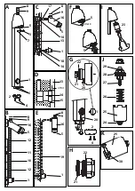
SPORTING douche suspendu (fig. E)

• Fixer la pomme de douche 

16 

au réseau.

• Pointer et fixer à 1,10 m du sol l’amorceur 

à l’aide des vis fournies (utiliser des chevilles adaptées au

matériau du mur).

• Raccorder l’amorceur 

et la pomme 

16 

avec un tube 6/8 

19

.

• Pour un fonctionnement correct, limiter la longueur du tube de liaison 6/8 et le nombre de coude

(maximum un coude).

• Monter le joint filtre 

8

fourni : il sert à protéger le clapet anti-retour 

9

. Raccorder au réseau d'eau

mitigée à 37°C. Vérifier l’étanchéité aux emmanchements.

F

MISE EN SERVICE

• Appuyez sur l’amorceur 

1

à plusieurs reprises (pour purger l’air) jusqu’à la stabilisation de la

temporisation (~30 sec. +5/-10) : les premiers cycles peuvent durer 5 à 7 minutes.
Au moment où l’on appuie sur l’amorceur 

1

, un jet d’eau sort sous ce dernier ce qui enclenche

l’amorçage hydraulique de la temporisation et donc l’ouverture instantanée de la douche. Une fois
l’amorceur 

1

relâché, le jet d’eau s’arrête.

• Le jet du diffuseur 

5

est orientable à 20° 

(fig. F)

et verrouillable en position à l’aide d’une pince à

circlips.

RAPPEL

• 

Nos robinetteries doivent être installées par des installateurs professionnels

en respectant

les réglementations en vigueur, les prescriptions des bureaux d’études fluides et règles de l’art.

• 

Respecter le diamètre des tuyauteries

permet d'éviter les coups de bélier ou pertes de

pression/débit. (Voir le tableau de calcul du catalogue et en ligne sur www.delabie.fr).

• 

Protéger l'installation

avec des filtres, antibéliers ou réducteurs de pression diminue la

fréquence d'entretien. (Pression conseillée : 0,8 à 5 bar).

• Poser des vannes d'arrêt 

à proximité des robinets facilite les interventions de maintenance.

• Les canalisations, robinets d’arrêt, de puisage et tout appareil sanitaire doivent être vérifiés aussi

souvent que nécessaire et au moins une fois par an.

Summary of Contents for NT 714

Page 1: ...r kits with automatic time flow shut off F GB DE PL NL F GB DE PL NL Purgez soigneusement les canalisations avant la pose et la mise en service du produit Vor Montage und Inbetriebnahme des Produkts die Anschlussleitungen regelkonform spülen Spoel zorgvuldig de leidingen vooraleer tot installatie of ingebruikname van het kraanwerk over te gaan Dokładnie wypłukać instalację przed montażem i uruchom...

Page 2: ...A 20 10 C D F G 1 2 H I J K 3 4 5 6 7 8 9 8 8 8 9 9 9 10 12 11 12 13 14 14 14 13 0 9mm 15 16 16 16 17 18 19 1 1 1 1 1 5 5 5 5 5 20 20 22 21 23 2 4 24 25 26 27 28 29 25 30 E B 22 21 ...

Page 3: ...r les colonnes 10 avec l amorceur 1 et le collier 11 Mettre les tubes PVC blancs 12 à l intérieur des colonnes Emmancher à fond l ensemble dans le trou situé sous la pomme 16 Pointer puis fixer avec les 2 vis chromées fournies utiliser des chevilles adaptées au matériau du mur Positionner le collier 11 au niveau du raccord central Pointer puis fixer avec les 4 vis fournies le collier 11 et l amorc...

Page 4: ...protéger le clapet anti retour 9 Raccorder au réseau d eau mitigée à 37 C Vérifier l étanchéité aux emmanchements F MISE EN SERVICE Appuyez sur l amorceur 1 à plusieurs reprises pour purger l air jusqu à la stabilisation de la temporisation 30 sec 5 10 les premiers cycles peuvent durer 5 à 7 minutes Au moment où l on appuie sur l amorceur 1 un jet d eau sort sous ce dernier ce qui enclenche l amor...

Page 5: ...lever à l aide d une pince à circlips fig I le mécanisme 23 fig I en veillant à bien récupérer le joint 24 fig J Retirer le piston 27 et le ressort 26 fig J Nettoyer l intérieur de la chemise 25 fig J K avec un chiffon puis la fine rainure intérieure 30 fig K avec une pointe non métallique et vérifier nettoyer les joints 28 et 29 fig J Remonter le mécanisme sans oublier le joint 24 fig J et alimen...

Page 6: ...vided use rawl plugs that are suitable for the wall type Position the collar 11 in the middle of the column to cover the joint Mark drill then fix the collar 11 and the push button starter 1 using the 4 screws provided use rawl plugs that are suitable for the type of wall Install the filter 8 supplied to protect the non return valve 9 and connect to the mixed water supply at 37 C recommended max 4...

Page 7: ...Install the supplied filter 8 to protect the non return valve 9 and connect to the mixed water supply at 37 C recommended max 41 C for the UK and Ireland Ensure that all the connections are waterproof GB COMMISSIONING Press the push button starter 1 several times to evacuate any air from the pipes until the automatic shut off delay is achieved 30 sec 5 10 the first few operations may last 5 7 minu...

Page 8: ...d remove the mechanism 23 fig I using a pair of circlip pliers fig I making sure that you remove the washer 24 fig J Remove the piston 27 and the spring 26 fig J Clean the interior of the delay case 25 fig J K with a cloth then the thin calibrated groove 30 fig K with a non metallic pointer and check clean the lip seal and O ring washers 28 and 29 fig J Replace the mechanism remembering to include...

Page 9: ... Schelle 11 zusammenbauen Die weißen PVC Rohre 12 in die Brauserohre einführen Alles in das Loch unter dem Brausekopf 16 schieben Anzeichnen dann mit den 2 mitgelieferten verchromten Schrauben befestigen Geeignete Dübel je nach vorhandener Wand wählen Schelle 11 in Höhe des mittigen Anschlusses positionieren Schelle 11 und Betätigungsknopf 1 anzeichnen und mit den 4 mitgelieferten Schrauben befest...

Page 10: ...indungsschlauchs 6 8 und die Anzahl der Bogen begrenzen maximal ein Bogen Mitgelieferte Siebdichtung 8 montieren Diese dient dem Schutz des Rückflussverhinderers 9 An Mischwasser 37 C anschließen Abdichtungen an den Verbindungen überprüfen DE INBETRIEBNAHME Betätigungsknopf 1 mehrmals drücken Entlüftung bis sich die Laufzeit stabilisert hat 30 sec 5 10 Die ersten Zyklen können 5 bis 7 Minuten daue...

Page 11: ...r O Ring im Selbstschlussmechanismus des Brausekopfs Wasser abstellen und Mechanismus 23 Abb I inklusive O Ring 24 Abb J mit einer Sicherungsringzange herausnehmen Kolben 27 und Feder 26 Abb J entnehmen Funktionsgehäuse 25 Abb J K innen mit einem weichen Tuch kalibrierte Nut 30 Abb K mit einem nicht metallischen spitzen Gegenstand reinigen O Ringe 28 und 29 Abb J überprüfen reinigen Mechanismus wi...

Page 12: ... Włożyć białe rury PVC 12 do wnętrza kolumn Wsadzić całość do otworu znajdującego się od spodu wylewki 16 Przyłożyć wylewkę do ściany i przymocować dwiema dostarczonymi chromowanymi śrubami używać kołków rozporowych odpowiednich dla danej ściany Ustawić obręcz 11 na wysokości środkowej złączki kolumn Przyłożyć do ściany i przymocować obręcz 11 i przycisk starter 1 za pomocą czterech dostarczonych ...

Page 13: ...elkę filtr 8 służy do ochrony zaworu przeciwpowrotnego 9 Podłączyć do zasilania wody zmieszanej ok 37 C Sprawdzić szczelność łączeń PL URUCHOMIENIE Nacisnąć wielokrotnie starter odpowietrzanie aż do uzyskania stabilności czasu wypływu 30 sek 5 10 Pierwszy cykl może trwać 5 do 7 minut W momencie naciśnięcia na przycisk starter 1 strumień wody wydostaje się spod niego co uruchamia natychmiastowe otw...

Page 14: ...ys I za pomocą szczypiec punktowych rys I Uważać aby nie zgubić uszczelki 24 rys J Wyciągnąć tłok 27 i sprężynę 26 rys J Wyczyścić szmatką wnętrze cylindra 25 rys J K natępnie rowek kalibrowany niemetalowym rylcem 30 rys K i sprawdzić wyczyścić uszczelki 28 i 29 rys J Włożyć mechanizm nie zapomnieć uszczelki 24 rys J i włączyć zasilanie wody Natrysk włącza się samoczynnie lub wypływ jest bardzo sł...

Page 15: ...de bevestigingsring 11 Monteer de witte PVC slangen 12 aan de binnenkant van de kolom Duw het geheel stevig in de opening voorzien onder de hoofddouche 16 Markeer en bevestig vervolgens de 2 meegeleverde verchroomde schroeven gebruik pluggen geschikt voor het materiaal waaruit de muur is gemaakt Plaats de bevestigingsbeugel 11 ter hoogte van het centraal koppelstuk Markeer en bevestig de beugel 11...

Page 16: ...ntal bochten beperken max 1 bocht Plaats de meegeleverde filterdichting 8 deze dient ter bescherming van de terugslagklep 9 Aansluiten op gemengd water van 37 C Controleer de waterdichtheid op de verbindingspunten NL INWERKINGSTELLING Duw meerdere malen op de drukknop 1 om te ontluchten tot een stabiele zelfsluiting 30 sec 5 10 wordt bekomen de eerste cycli kunnen 5 tot 7 minuten duren Op het ogen...

Page 17: ...t mechanisme 23 fig I en zorg ervoor dat u daarbij de O ring 24 fig J niet verliest Trek de zuiger 27 en de veer 26 fig J Reinig de binnenkant van de kraag 25 fig J K met een zachte doek en de gekalibreerde gleuf 30 fig K met een niet metalen naald en controleer de dichtingen 28 en 29 fig J Plaats het mechanisme terug en vergeet daarbij de dichting 24 fig J niet Sluit vervolgens het water weer aan...

Reviews: