Deif CGC 200 Operator'S Manual Download Page 15

4.1.2 Parameter list

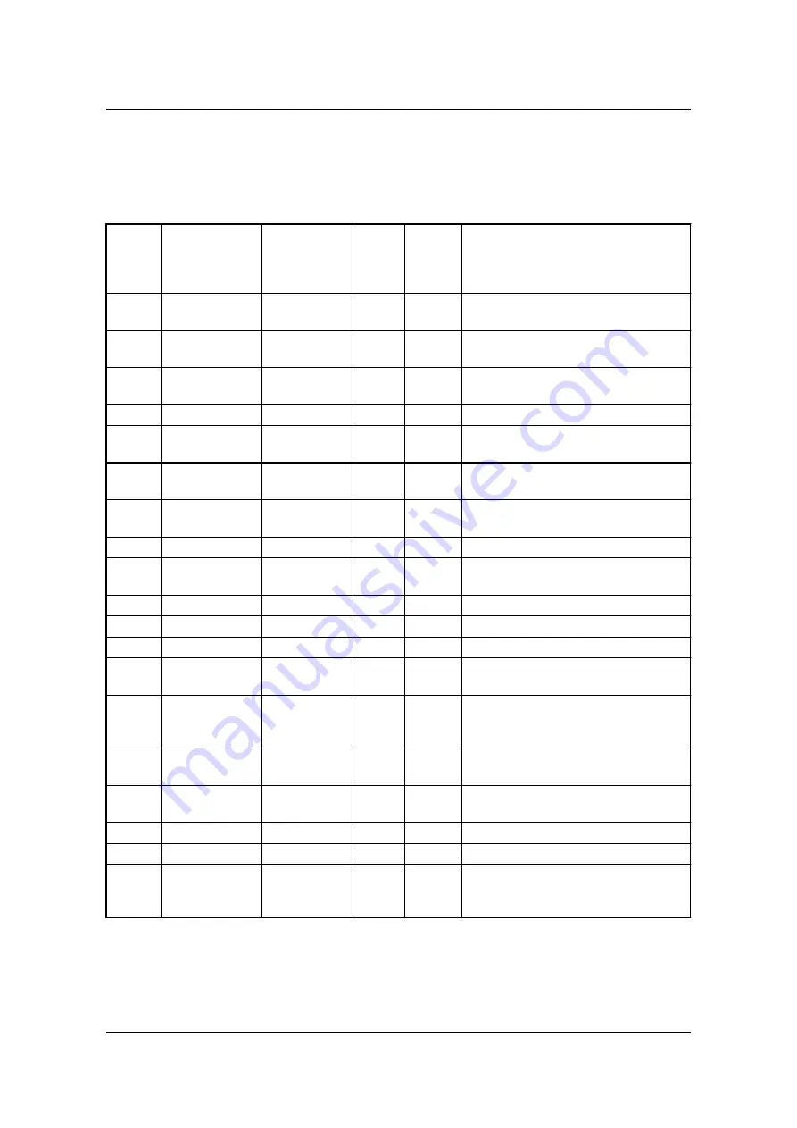
The parameters used by CGC 200 that can be changed from the controller front panel are listed in the table
below.

Param-

eter

num-

ber

Parameter

name

Range

De-

fault

value

Value
chos-

en*

Description

P00

Auto start delay

0 to 3600 s

1

Timer for starting using the Auto start
signal

P01

Auto stop delay

0 to 3600 s

1

Timer for stopping after the Auto start
signal is removed

P02

Start attempts

1 to 10

3

Number of start attempts in one start se-
quence

P03

Start prepare

0 to 300 s

0

Timer for start prepare

P04

Start on time

3 to 60 s

8

Timer for starter ON time during crank-
ing

P05

Start off time

3 to 60 s

10

Timer for starter OFF time before a new
start attempt is made

P06

Initial inhibit de-
lay

1 to 60 s

10

Timer for bypassing frequency and volt-
age shutdown during starting

P07

Idle start

0 to 3600 s

0

Timer for idle speed after starting

P08

GB close delay

3 to 3600 s

10

Timer for generator breaker close after
frequency and voltage OK

P09

Cooldown time

3 to 3600 s

10

Cooling down time

P10

Idle stop

0 to 3600 s

0

Timer for idle speed before stopping

P11

Extended stop

0 to 120 s

20

Timer for extended stop

P12

Stop failure

0 to 120 s

0

Maximum allowable time for stopping
the genset

P13

Number of teeth

10 to 300

118

The number of teeth on flywheel. This is
only used when MPU is selected as run-
ning detection (see 

P40

).

P14

Number of gen.
poles

2 to 32

4

The number of genset poles. This is
used in the frequency calculation.

P15

Hz/V OK delay

0 to 20.0 s

10.0

Voltage and frequency OK delay after
starting of genset

P16

G U >

30 to 360 V

264

Generator over-voltage protection

P17

G U <

30 to 360 V

196

Generator under-voltage protection

P18

G RPM <

0 to 6000
RPM

1200

Generator under-speed protection, if
running detection (see 

P40

) is RPM in-

put only

CGC 200 Operator's manual 4189340770
UK

Parameters

DEIF A/S

Page 15 of 43

Summary of Contents for CGC 200

Page 1: ...K 7800 Skive Tel 45 9614 9614 Fax 45 9614 9615 info deif com www deif com 14 9614 Fax 45 9614 9615 info deif com www deif com OPERATOR S MANUAL Compact Genset Controller CGC 200 Push buttons LEDs and...

Page 2: ...icons 10 2 4 5 Alarm icons 11 2 4 6 Display 11 3 Using the controller 3 1 Genset control mode and status 12 3 1 1 Genset control mode 12 3 1 2 Genset status 12 3 2 Basic tasks 12 3 2 1 Manual start 1...

Page 3: ...ameters 35 5 3 2 Configuring inputs and outputs 36 5 3 3 Reading from the controller 37 5 3 4 Writing to the controller 38 5 3 5 Firmware upgrade 39 6 Glossary 6 1 Abbreviations and terms 41 6 1 1 Abb...

Page 4: ...ator will also be able to monitor the system using the utility software 1 1 3 Revision information The letter at the end of the document number on the front page indicates the revision number of this...

Page 5: ...tion All the product technical documentation is available on the DEIF website Training You can ask for training Support You can call or email DEIF DEIF offers 24 hour support There may also be a local...

Page 6: ...if you need to remove the controller These precautions are no longer necessary once the controller is correctly installed and connected as re quired by the designer s wiring diagram 1 2 5 Legal infor...

Page 7: ...re is a shutdown alarm Tests all the LEDs and the full LCD display if pressed for more than three seconds in Stop mode Changes the mode to Manual if in Auto mode Start Starts the engine Manual mode on...

Page 8: ...tive non acknowledged alarm s present Mode OFF The unit is in manual mode RED STEADY The unit is in auto mode 2 4 Display 2 4 1 Display functions The display dimensions 20 mm x 40 mm shows readings an...

Page 9: ...tal genset running hours 2 4 3 Alarms If an alarm is activated it is shown on the screen by the alarm icon See the examples below Example of over speed alarm Example of auxiliary alarm CGC 200 Operato...

Page 10: ...tor voltage indication DC Battery voltage indication rpm Speed unit revolutions per minute kPa Oil pressure unit V Voltage unit Fuel level unit oC Temperature unit Hz Frequency unit H Accumulated runn...

Page 11: ...der voltage Auxilliary alarm Low fuel level 2 4 6 Display The display is a backlit LCD text display containing lines with characters and icons The display light intensity can be adjusted by pressing f...

Page 12: ...nformation on the genset statuses listed above 3 2 Basic tasks 3 2 1 Manual start To start the genset manually 1 Ensure that the controller is in Manual mode If the controller is in Auto mode the LED...

Page 13: ...3 2 7 Adjusting and testing the display The display light intensity can be adjusted by pressing for more than five seconds Keep pressing until the light level 0 to 7 is right for you 0 corresponds to...

Page 14: ...ters should not be changed without first consulting qualified and experi enced persons For more information about the controller functions and sequences that the parameters are based on see the Design...

Page 15: ...0 s 0 Timer for idle speed after starting P08 GB close delay 3 to 3600 s 10 Timer for generator breaker close after frequency and voltage OK P09 Cooldown time 3 to 3600 s 10 Cooling down time P10 Idle...

Page 16: ...6 4 See Table 1 Configurable output func tions P26 Relay 02 0 to 6 1 P27 Relay 03 0 to 6 2 P28 Digital input 1 0 to 10 5 See Table 2 Configurable input func tions P29 Digital input 1 timer 0 to 20 0...

Page 17: ...genset fre quency see P42 For RPM P13 and P41 must be de fined For frequency P42 must be defined P41 Remove starter RPM 0 to 3000 RPM 360 Minimum engine speed required for re moval of the starter and...

Page 18: ...Running minutes offset 0 to 59 mi nutes 0 Additional offset for the genset s running time timer 48 Running seconds offset 0 to 59 s 0 Additional offset for the genset s running time timer 49 Start att...

Page 19: ...ory default code is 2000 To enter the access code 1 Press to increase the value of the digit where the cursor is blinking You can use to de crease the value 2 Press to move to the next digit 3 When th...

Page 20: ...and PAGE DOWN together Enter parameter setting mode AUTO Increase value or next parameter ON Decrease value or previous parameter PAGE DOWN Next or Enter OFF Exit CGC 200 Operator s manual 4189340770...

Page 21: ...installed Microsoft Windows creates an incorrect USB driver if the controller is connected before the software is installed If you have this problem you need to find the correct USB driver in the sof...

Page 22: ...3 Click Software download on the left side of the page CGC 200 Operator s manual 4189340770 UK Using the Utility Software DEIF A S Page 22 of 43...

Page 23: ...Utility Software v 3 x from the drop down list A dialogue box opens with information about the most recent version of the software CGC 200 Operator s manual 4189340770 UK Using the Utility Software D...

Page 24: ...oading the software choose Run An installation wizard opens 2 Use the suggested default settings Note Option N refers to a TCP IP connection and is not relevant for CGC 200 3 When the installation is...

Page 25: ...he Settings icon on the toolbar 3 Under Communication in the Communication type field select Service port The other communica tion types are not relevant for CGC 200 4 In the Communication port drop d...

Page 26: ...t have a CGC 200 connected to your PC in order to see the Device Alarms Trending Parameters and Inputs Outputs pages CGC 200 Operator s manual 4189340770 UK Using the Utility Software DEIF A S Page 26...

Page 27: ...tory Trending Real time trending of measured values Parameters View and edit parameters configure inputs and outputs and set de lays and timers in Tree and List view modes Inputs Outputs Status of dig...

Page 28: ...lity Software Change or View the permission level Open a Utility Software or project file Print Print preview Settings Write firmware to the controller Batch read or write parameters to the controller...

Page 29: ...ion is shown Engine speed RPM Generator voltage Generator frequency Battery voltage Start attempts Running hours minutes and seconds Genset mode Auto or Manual and current status Standby Crank Fuel on...

Page 30: ...alarm on the Alarms page See the following screenshot for an example 5 2 4 Trending page You can see the real time trends for operating data on the Trending page See the following screenshot for an ex...

Page 31: ...To start real time trends 1 Open the Trending page CGC 200 Operator s manual 4189340770 UK Using the Utility Software DEIF A S Page 31 of 43...

Page 32: ...example is shown below 3 To set how often the trend updates as well as the trend width and memory select File then Settings then the Trending tab Set the values you want and click OK An example is sho...

Page 33: ...view the parameters are listed in groups as shown below Click on the group name to display all the parameters in that group You can edit the parameters using the sliders selectable text and values bo...

Page 34: ...om that in the controller For example you may have made a change and did not write the new value to the controller The change will not be updated in the controller until you write it to the controller...

Page 35: ...option In Tree view change the parameter by selecting the option you want from the drop down list In List view double click the parameter line you want to change A dialogue box containing the drop do...

Page 36: ...ion about how to write the changed values to the CGC 200 5 3 2 Configuring inputs and outputs Digital inputs and outputs can be configured in either Tree or List view In Tree view select the input or...

Page 37: ...the CGC 200 This information can also be stored in a file on the PC You can read from the controller by Connecting to the controller the utility software automatically reads the information in the CG...

Page 38: ...on the toolbar and select Read from device 2 The Batch job Reading dialogue box opens Select the information that you would like to read using the check boxes and click Run 3 A window opens Browse to...

Page 39: ...ribed below Restoring the controller information from a bak file using Restore Device Batch write function If a CGC 200 file has been saved on the PC it can be opened edited and then written to one or...

Page 40: ...he firmware file you want to use 3 Click Open Do not disconnect the power supply or the USB cable during the firmware upgrade Interrupt ing a firmware upgrade can make the controller unusable CGC 200...

Page 41: ...ouncil for Standardization Metrology and Certification IEC International Electrotechnical Commission IP Ingress Protection Rating or International Protection Rating The degree of protection against so...

Page 42: ...refers to the average AC voltage t Time U Voltage U is typically used as an abbreviation for voltage in Europe In other countries V may be used instead Unom Nominal voltage U is typically used as an a...

Page 43: ...nits used in the documentation Unit Name Measures A ampere Current C degrees Celsius Temperature g gram Mass H hour Time kPa kilopascal Pressure m metre Distance mm millimetre Distance ms millisecond...

Reviews: