background image

24

PS off

 4-20 mA

4,0

Abschal

tbetrieb manuel

l

U

th

50 V

VCSD off

PU off

OUT

Prinzipdarstel

lung


Betriebsmod

i

Selbsttest

VCSD aus /

Status

Fehler

status

Standar

dbetrieb

PS

Standby

check off

 4-20 mA

off

betriebsber

eit

Selbstest

VCSD aus /

Status

Fehler

status

PS on

U

th

check

 4-20 mA

4,0

Überwachungsbetrieb

off

Power

on

Selbsttest

VCSD aus /

Status

Fehler

status

PS on

 4-20 mA

4-20

Ableitbetrieb

Selbsttest

VCSD aus /

Status

Fehler

status

check off

Digital  IN

geschlossen

Digital  IN

geschlossen

Digital  IN

geschlossen

U

AC


?

U

AC


?

Digital  IN

geöffnet

U

th

check

Selbsttest

VCSD aus /

Status

Fehler

status

PS off

check off

 4-20 mA

22,8


PU

off

Abschal

tbetrieb F

ehler

Reset

or

Restart  nach 1h bzw

.

2 min

Fehler

status

Fehler

status

> U

th

< U

th

< U

th

> U

th

> U

th

check

-Batterie

-U

cap

-I temp

check

-Batterie -U

cap

-T

max

-I

dauer

-I

temp

-V

gate

VCSD on

VCSD off

VCSD on

VCSD on

PU off

PU off

Bedienfehler

OUT

OUT

OUT

OUT

U

th

on

PU on

U

th

off

U

ext

on

U

AC


>50 V

+

Summary of Contents for VCSD 40 IP65

Page 1: ...DE GB Publication No 1880 Update 09 17 Mat No 3006917 Copyright 2017 DEHN SÖHNE www dehn de Überspannungsschutz Bedienungs und Montageanleitung Spannungsgesteuerte Abgrenzeinheit VCSD 40 IP65 ...

Page 2: ...annungversorgung 11 4 1 3 Entfernen der Brücke VCSD aus 11 4 1 4 Einstellen der Ansprechschwelle 12 4 2 LED Anzeigen 13 4 3 Fehlerstatus 15 4 3 1 Fehlerzustände 15 4 3 2 Fehlerstatus Relais 16 5 Selbsttest 17 5 1 Abklemmen 17 5 2 Entladen 17 5 3 Externe Spannungsversorgung 17 6 VCSD aus 18 7 Analog OUT 19 8 Externe Spannungsversorgung 20 9 USB Schnittstelle 20 10 Technische Daten 21 11 Derating fü...

Page 3: ...derungen an der Abgrenzeinheit VCSD 40 IP65 führen zum Erlöschen des Gewährleistungsanspruches Vor Beginn jeder elektrischen Installation und Montage ist die Anwendungsnorm DIN VDE 0105 100 zum Arbeiten an elektrischen Anlagen und Betriebsmitteln zu beachten Nach Abklemmen des Pipeline und PE Anschlusses die Kondensatoren für mindestens 10 Sekunden durch Drücken des Tasters SVN 311 entladen Achtun...

Page 4: ...Abgrenzeinheit VCSD 40 IP65 folgende überspannungsbedingte Auswirkungen erfasst Vermeidung undefinierter blitzbedingter Durch und Überschläge von Isolationsstrecken Überspannungen durch Blitzereignisse werden begrenzt die in diesem Zusammenhang auftretenden Blitzströme werden gegen die örtliche Erde abgeleitet Sachschutz Vermeidung gefährlicher Berührungsspannung an zugänglichen Stellen Gefährliche...

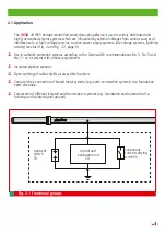
Page 5: ...ch Fig 2 1 und Fig 2 2 Seite 6 Einsatz in KKS Anlagen entsprechend der AfK Empfehlung Nr 3 Nr 5 und 11 bzw Anlagen mit ähnlichen Anforderungen Isolierte Pipelineabschnitte Offene Erdung von Kabelschirmen an zugänglichen Stellen Korrosionsfreier Zusammenschluss von erdgebetteten metallenen Anlagen z B Erdungsanlagen mit einem Fundamenterder Verbindung verschiedener getrennt wirkender Erdungssysteme...

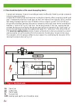
Page 6: ...r bzw temporärer Zeitbereich führen zu thermischen Überlastung Deshalb muss bei solchen Vorgängen eine Entlastungsschaltung den Ableitvorgang übernehmen d h der Ableit strom über die Funkenstrecke muß vollständig auf die Entlastungsschaltung kommutieren sobald die Überspannung den transienten Zeitbereich übersteigt Diese Entlastungsschaltung PU besteht bei der Abgrenzeinheit VCSD 40 IP65 aus Leist...

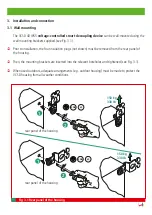
Page 7: ...e müssen jedoch die vier Isolierstopfen nicht abgebildet aus der Gehäuserückwand entfernt werden Danach wird die entsprechende Befestigungslasche an die jeweilige Bohrdurchführung herangeführt durchgeführt und festgeschraubt Beachte hierzu Fig 3 1 Das Gehäuse des VCSD ist im Außenbereich durch entsprechende Maßnahmen z B Outdoorgehäu se vor Witterungseinflüssen zu schützen Fig 3 1 Gehäuserückwand G...

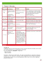
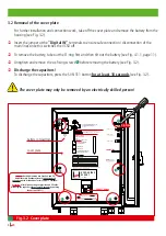
Page 8: ...h Drücken des Tasters SVN 311 entladen Attention After disconnecting the pipeline and PE cable discharge the capacitors for at least 10 seconds by pushing the button SVN 311 Binär Code Beschreibung Binary code Description 0 0 1 Dauerhafter Überstrom Continuous overcurrent 0 1 0 Defekte Funkenstrecke Faulty spark gap 0 1 1 Elektronikfehler Electronic failure 1 0 0 Niedrige Batteriespannung Low batt...

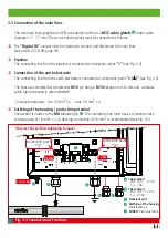
Page 9: ... Erder kommend wird am Anschlusspunkt 2 angeschlossen siehe Fig 3 3 Der Anschluss der Leitungen erfolgt am jeweiligen M10 Anschlussbolzen mittels einer M10 Sechskantmutter Hierfür wird ein Rohrkabelschuh Anschluss empfohlen Anschlussquerschnitt min 35 mm2 Cu max 50 mm2 Cu Gehäuseerdung Schutzpotential Der Anschluss erfolgt über den M8 Gewindebolzen Die Anschlussleitung muss einen Mindest querschni...

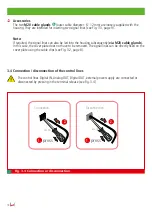
Page 10: ...raubungen M20 auch nachträg lich ins Gehäuse eingeführt werden Eine Demontage der Abdeckplatte ist hierbei nicht erforderlich Die Signalleitungen können direkt auf der Abdeckplatte mittels der Kabel Clips befestigt werden siehe Fig 3 2 Seite 8 3 4 An bzw Abklemmen der Steuerleitungen Das An bzw Abklemmen der Steuerleitungen Digital IN Analog OUT Digital OUT ext Spannungs versorgung erfolgt durch d...

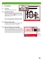
Page 11: ...1 Die Polarität ist zu beachten 4 1 2 Externe Spannungsversorgung Gegebenenfalls externe Spannungsversorgung anlegen siehe Pkt 8 Seite 20 4 1 3 Entfernen der Brücke am Eingang Der VCSD wird in der Betriebsart VCSD aus ausgeliefert Durch Entfernen der Brücke vom Eingang Digital IN wird diese Betriebsart been det und das Gerät ist betriebsbereit Anschließend kann eine externe Steuerleitung an den Kl...

Page 12: ...e Drehkodierschalter 3 Loslassen der Taste Freigabe Schwellenspannung 4 Übernahme des neuen Schwellenwertes Es sind Werte von 3 50V zulässig Bei Unterschreiten wird 3V bei Überschreiten 50V eingestellt und die Status LED blinkt wie folgt Status d h ungültige Schwelle während des Überwachungsbetriebs abwechselnd gelb grün Status d h ungültige Schwelle während des Ableitbetriebs abwechselnd gelb rot...

Page 13: ...tterie siehe Pkt 1 Seite 3 Status Status LED grün blinkend Beeinflussung oder ext Versorgungsspannung vorhanden aber keine Überschreitung der einge stellten Ansprechschwelle Überwachungsbetrieb aktiv Status Status LED rot blinkend Beeinflussung vorhanden Ansprechschwelle über schritten Ableitbetrieb aktiviert Status Status LED grün gelb oder rot gelb blinkend Bedienfehler liegt vor ungültiger Wert e...

Page 14: ... zu Status LED Taste Selbsttest wurde gedrückt Selbsttest läuft Externe Spannung liegt an Selbsttest LED 5 Sekunden grün leuchtend Selbsttest OK Gerät ist in Ordnung Selbsttest LED 5 Sekunden gelb leuchtend Selbsttest abgebrochen Pipelinepotential liegt noch an Gerät zuerst abklemmen Selbsttest LED 5 Sekunden rot leuchtend Selbsttest nicht OK Gerät ist defekt Es wechselt automatisch in den Fehlers...

Page 15: ... Gehäuse bzw an der Abdeckplatte untereinander angeordnet Die binäre Auswertung erfolgt über die rechts der LED s zugeordneten Platzhalter siehe Fig 4 3 1 Funktionsbeispiel Die oberste LED leuchtet nicht steht für Binärcode 0 Die mittlere LED leuchtet nicht steht für Binärcode 0 Die unterste LED leuchtet rot steht für Binärcode 1 Es ergibt sich somit ein Binärcode von 0 0 1 Gemäß der Binärcode Tab...

Page 16: ...Schwellenwertes mehr statt Ein externes Fehlerstatus Relais z B Schaltschütz kann zur Erhaltung des Personenschutzes übergeordnet angeschlossen werden siehe Fig 4 3 2c Nach einer Fehleranalyse siehe Tabelle 1 Seite 23 und ggf Beseitigung des Fehlers kann der Fehlerstatus durch Drücken der Taste Rücksetzen Fehlerstatus wieder beendet werden siehe Fig 4 3 2b Das Gerät geht wieder in seinen Normalbet...

Page 17: ...ite 8 beschrieben müssen zum Abklem men die beiden M10 Sechskantmutter vom Anschlusspunkt 1 und 2 abgeschraubt werden Danach können die beiden Leitungen vom jeweiligen M10 Anschlussbolzen abgenommen werden siehe hierzu Fig 3 3 Seite 9 5 2 Entladen Zum Entladen der Kondensatoren muss der Taster SVN 311 mindestens 10 Sekunden gedrückt werden siehe Fig 5 2 5 3 Externe Spannungsversorgung Anlegen der ...

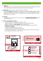
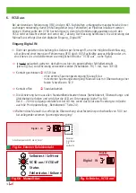
Page 18: ...CSD aus siehe Fig 6c Ist nicht galvanisch getrennt deshalb muss hier ein potentialfreier Schließerkontakt siehe Fig 6a zur Aktivierung verwendet werden Schaltdaten 9 V 1 mA max 100 Ω Kontakt geschlossen VCSD Aus ohne externe Spannungsversorgung Manuell Aus mit externer Spannungsversorgung Manuell Aus mit Überwachung einer festen Schwelle von 50 V Kontakt offen Standardbetrieb Die Aktivierung kann ...

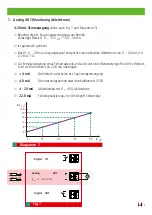
Page 19: ...50 50 mA Ist galvanisch getrennt Das DC 4 20 mA Ausgangssignal entspricht einem aktuellen Ableitstrom von 0 40 Aeff d h 0 4 mA 1A Zur Fernsignalisierung eines Fehlerzustands am Gerät der einen Bedienereingriff vor Ort erfordert wird ein Alarm Wert von 22 8 mA übertragen 4 mA Drahtbruch oder keine ext Spannungsversorgung 4 0 mA Überwachungsbetrieb oder Abschaltbetrieb VCSD 4 20 mA Ableitbetrieb mit...

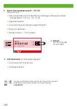
Page 20: ...50 mA Ist galvanisch getrennt Ist zur Ausführung eines Selbsttest zwingend erforderlich Ersetzt nicht die Batterie Versorgt auch den 4 20 mA Ausgang Fig 8 z B Netzteil Typ PSU DC24 30W Art Nr 910499 9 USB Schnittstelle nur für Hersteller zugänglich In Form einer USB 2 0 Typ B Buchse Ist galvanisch getrennt Das Gerät und die Batterien dürfen nicht über den Hausmüll entsorgt werden Weiterführende In...

Page 21: ...itstrom temporär 16 7 Hz 50 Hz 60 Hz Ableitstrom stationär 16 7 Hz 50 Hz 60 Hz Begrenzungsspannung transient bis 1 ms Begrenzungsspannung temporär ACrms 1 20 ms Begrenzungsspannung temporär ACrms 20 100 ms Begrenzungsspannung temporär ACrms 100 200 ms Begrenzungsspannung stationär ACrms 200 ms Frequenzbereich AC Max zulässige DC Spannung im Ableitbetrieb Max Leckstrom im Nichtableitbetrieb bei Tam...

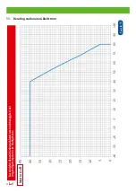
Page 22: ...22 T amb in C I stat in A rms 11 Derating stationärer Ableitstrom Derating für den stationären Ableitstrom in Abhängigkeit der Umgebungstemperatur im Stahlgehäuse I stat in A eff ...

Page 23: ...hat ange sprochen Selbsttestfehler Leistungselektronik defekt Anzeige nach Betätigung der Selbsttest Taste solange eine externe Versorgungsspannung angeschlossen ist leuchtet der Fehlerstatus 1 1 0 zusam men mit der Selbsttest LED rot nach Abklemmen der externen Versorgungsspan nung erlischt die Selbsttest LED und es leuchtet nur noch der Fehlerstatus 1 1 0 Reset Taste betätigen bei erneutem Auftr...

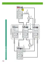
Page 24: ...A 4 20 Ableitbetrieb Selbsttest VCSD aus Status Fehlerstatus check off Digital IN geschlossen Digital IN geschlossen Digital IN geschlossen U AC U AC Digital IN geöffnet U th check Selbsttest VCSD aus Status Fehlerstatus PS off check off 4 20 mA 22 8 PU off Abschaltbetrieb Fehler Reset or Restart nach 1h bzw 2 min Fehlerstatus Fehlerstatus U th U th U th U th U th check Batterie U cap I temp check...

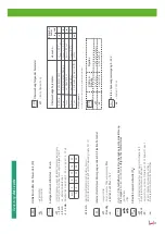
Page 25: ...Fehlerstatus geschlossen offen Aktuelle Ansprechschwelle U th off es findet keine Überwachung der Ansprechschwelle statt check die Ansprechschwelle wird überwacht 50 ausgesetzt es wird eine Schwelle von 50 V überwacht wenn eine ext Spannungsversorgung anliegt on die Ansprechschwelle wurde übeschritten Bedeutung der i con s PS check Überwachung folgender Parameter off Keine Überwachung Externe Spann...

Page 26: ...zeige am Gerät bis eine Freigabe Korrektur erfolgt Bleiben unverändert entsprechend der Betriebsart während Überwachungsbetrieb während Ableitbetrieb PS PU check 4 20 mA VCSD Begriffserläuterungen Digital IN geschlossen Durch Schließen des digitalen Eingangs wird das Gerät gezielt in den Abschaltbetrieb gebracht auch bei betriebsbereit bis der Kontakt wieder geöffnet wird Das Gerät wechselt dabei ...

Page 27: ...ery Netzteil Typ PSU DC24 30W Art Nr 910499 Überspannungsschutz Digital IN Typ BXT BAS Art Nr 920 300 und Typ BXT ML4 B 180 Art Nr 920 310 Digital OUT Typ BXT BAS Art Nr 920 300 und Typ BXT ML4 B 180 Art Nr 920 310 Analog OUT Typ BXT BAS Art Nr 920 300 und Typ BXT ML4 BE 24 Art Nr 920 324 ...

Page 28: ...Überspannungsschutz DEHN SÖHNE Hans Dehn Str 1 Tel 49 9181 906 0 Blitzschutz Erdung GmbH Co KG Postfach 1640 www dehn de Arbeitsschutz 92306 Neumarkt DEHN schützt Germany ...

Page 29: ...tion No 1880 Update 09 17 Mat No 3006917 Copyright 2017 DEHN SÖHNE www dehn international com Surge protection Instruction for use installation instructions Voltage controlled smart decoupling device VCSD 40 IP65 ...

Page 30: ...4 1 2 External power supply 11 4 1 3 Removal of the VCSD off jumper 11 4 1 4 Setting the response threshold 12 4 2 LED indications 13 4 3 Failure mode 15 4 3 1 Fault states 15 4 3 2 Failure mode relay 16 5 Self test 17 5 1 Disconnection 17 5 2 Discharge 17 5 3 External power supply 17 6 VCSD off 18 7 Analog OUT 19 8 External power supply 20 9 USB interface 20 10 Technical data 21 11 Derating for t...

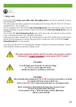
Page 31: ...g with or modification of the VCSD 40 IP65 smart decoupling device will void warranty In Germany the DIN VDE 0105 100 application standard Operation of electrical installations must be observed before starting any electrical installation work After disconnecting the pipeline and PE connection the capacitors must be discharged for at least 10 seconds by pressing the SVN 311 button Attention If no LE...

Page 32: ... overvoltage related effects are detected Prevention of undefined lightning related puncture and flashover at insulating clearances Lightning overvoltage is limited and the associated lightning currents are discharged to local earth protection of material assets Prevention of dangerous touch voltages at accessible locations Dangerous touch voltages are limited below the maximum permissible touch vol...

Page 33: ...rotection systems according to the German AfK recommendations No 3 No 5 and No 11 or in systems with similar requirements Insulated pipeline sections Open earthing of cable shields at accessible locations Corrosion free connection of buried metal systems e g earth termination systems to a foundation earth electrode Connection of different isolated earth termination systems e g foundation earth ele...

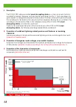
Page 34: ...eir high energy discharge capacity in case of impulses in the µs range e g some 10 kA 10 350 µs Long duration discharge processes long term or temporary time range cause thermal overload and therefore a relief circuit has to take over the discharge process in this case meaning that the complete discharge current flowing through the spark gap has to commute to the relief circuit as soon as the overv...

Page 35: ...ee Fig 3 1 Prior to installation the four insulation plugs not shown must be removed from the rear panel of the housing Then the mounting brackets are inserted into the relevant boreholes and tightened see Fig 3 1 When used outdoors adequate arrangements e g outdoor housing must be made to protect the VCSD housing from all weather conditions rear panel of the housing rear panel of the housing Fig ...

Page 36: ...hlusses die Kondensatoren für mindestens 10 Sekunden durch Drücken des Tasters SVN 311 entladen Attention After disconnecting the pipeline and PE cable discharge the capacitors for at least 10 seconds by pushing the button SVN 311 Binär Code Beschreibung Binary code Description 0 0 1 Dauerhafter Überstrom Continuous overcurrent 0 1 0 Defekte Funkenstrecke Faulty spark gap 0 1 1 Elektronikfehler El...

Page 37: ...e earth electrode is connected at connection point 2 see Fig 3 3 The lines are connected at the relevant M10 pin using a M10 hexagon nut To this end a tubular cable lug connection is recommended Cross sectional area min 35 mm2 Cu max 50 mm2 Cu Earthing of the housing protection potential Connection is made via the M8 threaded pin The connecting line must have a minimum cross sectional area of 16 m...

Page 38: ...o the housing subsequently via M20 cable glands In this case the cover plate does not have to be removed The signal lines can be directly fixed on the cover plate using the cable clips see Fig 3 2 page 8 3 4 Connection disconnection of the control lines The control lines Digital IN Analog OUT Digital OUT external power supply are connected or disconected by pressing in the terminal release see Fig ...

Page 39: ...The correct polarity should be observed 4 1 2 External power supply If required the device must be operated via the external power supply see 8 page 20 4 1 3 Removal of the jumper at the input The VCSD is delivered in the VCSD off mode When removing the jumper from the Digital IN input this operating mode is ended and the device is operational After that an external control line can be connected t...

Page 40: ...via the rotary coding switch 3 Release the Release threshold voltage button 4 The new threshold value is set Values from 3 to 50 V are permitted If these values are undercut exceeded 3 V 50 V is automatically set The status LED flashes as follows Status i e impermissible threshold in the moni toring mode alternating yellow and green Status i e impermissible threshold in the discharge mode alternati...

Page 41: ...hreshold is not exceeded monitoring mode is active Status Status LED flashes red Interference is present response threshold is exceeded discharge mode is active Status Status LED flashes green yellow or red yellow An operating error is present Invalid value is set response threshold is too high or low The changed value of the response threshold has not been confirmed green yellow in the monitoring mo...

Page 42: ...ashes yellow alternating with status LED Self test button was pressed Self test is running external voltage is applied Self test LED lights up green for 5 seconds Self test OK Device is OK Self test LED lights up yellow for 5 seconds Self test is interrupted pipeline potential is still present disconnect the device first Self test LED lights up red for 5 seconds Self test not OK Device is faulty Au...

Page 43: ... binary code 0 see Fig 4 3 1 The failure mode LEDs are arranged vertically in the housing respectively on the cover Binary evaluation is performed by means of the place holders on the right side of the LEDs see Fig 4 3 1 Example The top LED does not light up stands for binary code 0 The centre LED does not light up stands for binary code 0 The lower LED lights up red stands for binary code 1 This ...

Page 44: ... the threshold value is no longer monitored An external failure mode relay e g switch contactor can be connected on a higher level to ensure personal protection see Fig 4 3 2c After analysing see Table 1 page 23 and eliminating the fault if any the failure mode can be reset by pressing the Reset failure mode button see Fig 4 3 2b The device returns to normal operation and the external failure mode...

Page 45: ...emoving the cover plate as described in 3 2 on page 8 unscrew the two M10 hexagon nuts from connection point 1 and 2 Then remove the two lines from the relevant M10 pin see Fig 3 3 page 9 5 2 Discharge To discharge the capacitors press the SVN 311 button for at least 10 seconds see Fig 5 2 5 3 External power supply Apply the external supply voltage 9 32 V d c Remove the VCSD off jumper at Digital ...

Page 46: ...possible interference for example during a DCVG ACVG survey carried out by cathodic protection specialists or to ensure safe connection and disconnection VCSD off jumper see Fig 6c Not galvanically isolated and therefore a floating make contact see Fig 6a must be used for activation switching data 9 V 1 mA max 100 Ω Contact closed VCSD off Without external power supply manual off With external powe...

Page 47: ...ally isolated The 4 20 mA d c output signal corresponds to an actual discharge current of 0 40 Arms that is 0 4 mA 1 A An alarm value of 22 8 mA is transmitted for remotely signalling a failure mode at the device which requires on site operator intervention 4mA Wire breakage or no external power supply 4 0 mA Monitoring or switch off mode VCSD 4 20 mA Discharge mode with a discharge current of 0 4...

Page 48: ... External power supply 9 32 V d c see also Fig 8 Continuous and undisturbed supply of the device Permissible range 9 32 V d c 150 50 mA Galvanically isolated Required for performing a self test Does not replace the battery Also supplies the 4 20 mA output Fig 8 e g power supply unit of type PSU DC24 30W Part No 910 499 9 USB interface only accessible to manufacturer In the form of a USN 2 0 type B...

Page 49: ...e of protection Digital output type of contact Switching capacity a c Switching capacity d c Digital input type of contact Contact data Cross sectional area of the signal lines Dimensions Weight PU 923 401 100 kA 100 kA 1 1 kArms up to 200 ms 1 500 Arms up to 1s 40 Arms permanently 2 1 25 kV 940 V 1 kV acc to AfK 3 660 V 1 kV acc to AfK 3 400 V 1 kV acc to AfK 3 max 50 V adjustable from 3 50 V 16 ...

Page 50: ...22 T amb in C I stat in A rms 11 Derating for a long term discharge current Derating for the long term discharge current as a function of the ambient temperature in the steel housing ...

Page 51: ...ed Self test failed Faulty power electronics indication after pressing the self test button as long as the external supply voltage is connected the failure mode 1 1 0 lights up in combination with the self test LED red after disconnecting the external supply voltage the self test LED goes out and only the failure mode 1 1 0 lights up Press the Reset button if this fault occurs again compare the te...

Page 52: ...n 4 20 mA 4 20 discharge mode Selbsttest VCSD aus Status Fehlerstatus check off Digital IN closed Digital IN closed Digital IN closed U AC U AC Digital IN open U th check Selbsttest VCSD aus Status Fehlerstatus PS off check off 4 20 mA 22 8 PU off fault in switch off mode reset or restart after 1h or 2 min failure mode failure mode U th U th U th U th U th check battery U cap I temp check battery ...

Page 53: ...f failure mode closed open Actual response threshold U th off response threshold is not monitored check response threshold is monitored 50 stopped a threshold of 50 V is monitored if the device is operated via the external power supply on response threshold was exceeded Meaning of the icons PS check Monitoring of the following parameters off no monitoring External power supply 9 32 V on connected ...

Page 54: ...g indication appears on the device unchanged according to the operating mode in monitoring mode in discharge mode PS PU check 4 20 mA VCSD Terms and definitions D OUT U th Digital IN closed If the digital input is closed the device is put into the switch off mode also if it is operational until the contact is opened again The device directly changes back to the currently required operating mode Fai...

Page 55: ...attery Power supply unit PSU DC24 30W Part No 910 499 Surge protective devices Digital IN BXT BAS Part No 920 300 and BXT ML4 B 180 Part No 920 310 Digital OUT BXT BAS Part No 920 300 and BXT ML4 B 180 Part No 920 310 Analog OUT BXT BAS Part No 920 300 and BXT ML4 BE 24 Part No 920 324 ...

Page 56: ...Surge Protection DEHN SÖHNE Hans Dehn Str 1 Tel 49 9181 906 0 Lightning Protection GmbH Co KG Postfach 1640 www dehn international com Safety Equipment 92306 Neumarkt DEHN protects Germany ...

Reviews: