background image


28 

www.degometal.com 


3. Tool preparation 

 
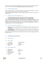
Please read the following important notes carefully before using the rivet tool:  

Before  replacing  nose  pieces  and  mandrels,  battery  must  be  removed  from  the  tool,  otherwise 
injury be caused !! 

Then select the nose piece and nose housing that matches the size of the nut. 
 

3.1 

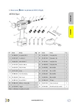
Replacing accessories (GO3312 fig.A) 

 
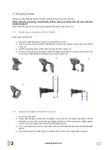
Nose piece and mandrel 


Reconfirm that the battery has been removed from the tool 


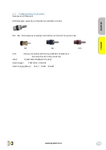
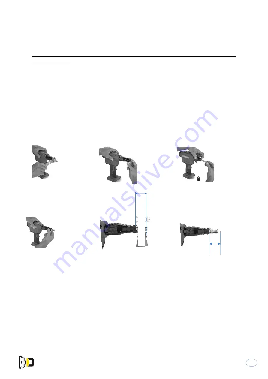
Loosen counter nut 2 by using the double head nut wrench 20 (Fig. 1) and screw out mandrel 
1 (Fig. 2) 


Hold the replacing sleeve 4 back and unscrew mandrel 1 (Fig. 3,4) 


Find out corresponding nose piece, hold the replace sleeve back to screw it into the tool, and 
screw the corresponding mandrels with counter nut (Fig. 3,4). 


3.2 

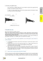
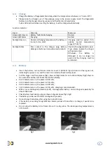
Adjust the length of Mandrel X (Fig. 5) 


Loosen counter nut 2. 


Rotate  the nosepiece  1 based on the length  of the  rivet  nut  and adjust the length X of the 
Mandrel to  ensure  that  all  threads  are  engaged;  the front  of  the mandrel  is  slightly  higher, 
and the rivet nut clings to the front of the nosepiece (Fig. 6). 


If it is an sealed type rivet nut, then make full use of the external and internal thread depth 
(Fig. 5) 


Use double head nut wrench (Fig. 1) to tighten the counter nut 2 slightly. Do not rotate. 


Summary of Contents for GO 3312

Page 1: ...DE SÉCURITÉ ET MODE D EMPLOI SAFETY INSTRUCTIONS AND DIRECTIONS FOR USE Équipé en standard de M4 à M10 M3 M12 en option Equipped in standard with M4 to M10 M3 M12 optional Vidéo Utilisation GO3312 Scannez Scan it ...

Page 2: ...A 14 5 3 1 Note importante si les erreurs suivantes se produisent 14 5 3 2 Note importante si les erreurs suivantes se produisent 14 6 CHARGEUR RAPIDE ET BATTERIE 14 6 1 SPECIFICATION 14 6 1 1 Chargeur rapide 14 6 1 2 Charge rapide de la batterie 14 6 2 INFORMATION SUR LA SECURITE 15 6 2 1 Chargeur rapide 15 6 2 2 Batterie rapide rechargeable 15 6 3 CHARGE 16 6 4 BATTERIE 16 6 5 REGLES DE SECURITE...

Page 3: ... RIVET NUT MANUALLY GO3312 FIGA 31 5 3 RIVETING GO3312 FIGA 32 5 3 1 Important note if following mistakes occur 32 5 3 2 Important note if following mistakes occur 32 6 QUICK CHARGER AND BATTERY 32 6 1 SPECIFICATION 32 6 1 1 Quick charger 32 6 1 2 Quick charging battery 32 6 2 SAFETY INFORMATION 33 6 2 1 Quick charger 33 6 2 2 Quick chargeable battery 33 6 3 CHARGE 34 6 4 BATTERY 34 6 5 SAFETY RUL...

Page 4: ...4 www degometal com ...

Page 5: ... Z21009H00 Embout M8 1 4 L41209H00 Molette de réglage 1 28 L23038H00 Tirant M4 1 0 L40117H00 Crochet 1 29 L23037H00 Tirant M5 1 9 Z40806H00 Indicateur de Course 1 30 L23036H00 Tirant M6 1 20 Z41104H00 Capot arrière 1 31 L23035H00 Tirant M8 1 11 Z4080ZH00 Corps GO3312 1 23 Z40509H00 Chargeur 1 22 Z40828H00 Batterie 8 cell 4 0Ah 1 34 F60273H00 Clé hexagonale M5 1 32 L41530H00 Gâchette 1 35 L41244H00...

Page 6: ...e de l outil N utilisez pas l outil comme outil de frappe Rangez l outil dans un endroit sec et fermé hors de la portée des enfants Portez toujours des lunettes de protection lors de l utilisation de l outil Les équipements de protection individuelle tels que les vêtements de protection contre les produits chimiques les gants les casques de protection les chaussures antidérapantes les bouchons d o...

Page 7: ...sur l outil Les embouts et les mandrins M5 M6 et M8 sont rangés dans la mallette M5 M6 M8 Outil Un tournevis hexagonal SW5 et un SW16 21 à double tête sont dans la mallette Crochet plié et intégré au corps Chargeur rapide 100V 240V 50 60 Hz Charge rapide de la batterie 14 4 V 4 0 Ah 57 6Wh FRANCAIS ENGLISH ...

Page 8: ...t M5 1 9 Z40806H00 Indicateur de Course 1 26 Z211010H00 Embout M6 1 10 L20127H00 Vis à tête cylindrique à empreinte cruciforme 1 27 Z21009H00 Embout M8 1 11 Z4080ZH00 Corps GO3312 1 28 L23038H00 Tirant M4 1 12 L40151H00 Câble souple d affichage de course 1 29 L23037H00 Tirant M5 1 13 L40820H00 Câble plat flexible de capteur 1 30 L23036H00 Tirant M6 1 14 Z40808H00 Carte PCB 1 31 L23035H00 Tirant M8...

Page 9: ...9 www degometal com GO3312 fig B FRANCAIS ENGLISH ...

Page 10: ...g 2 Tenir le manchon de remplacement 4 en arrière et dévisser le mandrin 1 Fig 3 4 Prenez le nez correspondant maintenez le manchon de remplacement en place pour le visser dans l outil et vissez les mandrins correspondants avec le contre écrou Fig 3 4 3 2 Ajustement de la longueur du mandrin X Fig 5 Desserrez le contre écrou 2 Faites tourner l embout 1 en fonction de la longueur de l écrou et régl...

Page 11: ...éros de LED 2 4 6 sont allumés la puissance est de 75 5 2 numéros de LED 2 sont allumés la puissance est de 50 5 1 numéro de LED 2 allumé l alimentation est à 25 5 le chargement est recommandé 4 2 Régler la puissance de traction Réglez la puissance de traction comme décrit ci dessous 1 Sélectionnez la puissance de traction en utilisant la carte de paramétrage rapide fournie 2 Sélectionnez Normal L...

Page 12: ...ppuyez sur l interrupteur Fig 2 et le déverrouillage Les voyants LED bleu L et Vitesse 2 sont toujours allumés Fig 3 indiquant que l outil est en marche et que la course est préréglée sur 0 2mm Appuyez sur l interrupteur Fig 4 puis relâchez le Les voyants LED bleu L et de vitesse 4 de l afficheur de fonction sont toujours allumés indiquant que la course a été commutée avec succès sur 2 4 mm Comme ...

Page 13: ...onnez L pour la tension et 4 pour la course 5 1 Placez un écrou au bout du mandrin 3 voir points clés 3 1 et 3 2 fig 5 6 Il est recommandé de visser manuellement l écrou sur environ un demi tour pour faciliter l insertion du mandrin 3 Poussez manuellement l écrou sur l embout reportez vous à la Fig 1 ci dessus et le visser jusqu à ce qu il soit bien ajusté à l embout Le processus de vissage se ter...

Page 14: ...xagonal SW5 stocké dans l hexagone interne situé à l arrière de l outil et vissez à gauche avec précaution utilisez un coupe fil si nécessaire pour serrer l écrou et l empêcher de bouger l écrou sera dévissé Reportez vous au point clé 7 du dépannage 7 1 L écrou ne peut pas être dévissé 5 3 2 Note importante si les erreurs suivantes se produisent L écrou n est pas correctement vissé ni ajusté à la ...

Page 15: ...n endroit sec et fermé hors de la portée des enfants Ne placez jamais d objet métallique dans la zone de charge pour éviter tout court circuit Si le chargeur est installé au mur assurez vous que la batterie ne tombera pas du chargeur en raison d influences externes telles que des vibrations Ce chargeur ne doit pas être utilisé par des personnes ayant une déficience physique ou intellectuelle ou de...

Page 16: ... charge doit être stoppée 6 4 Batterie Insérez la batterie Le capot de l indicateur d incident à LED rouge 9 GO3312 fig A clignote puis s éteint indiquant que l appareil est sous tension et que l outil est sous tension normalement Vérifiez le niveau de la batterie Appuyez sur la gâchette puis relâchez fig1 le voyant à chiffres bleu sur l affichage de fonction fig2 reste allumé pendant 3 secondes p...

Page 17: ...être effectuée par un atelier de maintenance agréé ou le SAV Degometal au moins une fois tous les deux ans Si l outil est utilisé fréquemment une maintenance avec un intervalle court est recommandée 7 2 Réparation En principe le fabricant devrait être responsable de la garantie Si la garantie est expirée l entretien ne doit être effectué que par des professionnels Si les règles d installation et d...

Page 18: ...ivoter dans le sens contraire des aiguilles d une montre pour desserrer le capot arrière 8 2 Exposer le trou hexagonal à l arrière de l outil 3 Insérez le tournevis hexagonal SW5 stocké dans le trou hexagonal faites le tourner avec précaution dans le sens inverse des aiguilles d une montre pour le desserrer dévisser et remplacer l écrou à sertir 4 Le cas échéant utilisez la clé à six pans creux fo...

Page 19: ...euillez retirer la batterie Lorsque l outil n est pas utilisé veuillez le conserver dans sa mallette et le conserver dans un endroit sec et hors de la portée des enfants Lors de l utilisation de l outil l opérateur doit porter des lunettes de protection un casque des gants et tout autre équipement de protection individuelle nécessaire Lors de l utilisation de l outil veuillez vous assurer que les ...

Page 20: ...s d usure ne sont pas couvertes par la garantie Le fabricant n est pas responsable des problèmes de qualité causés par une utilisation incorrecte En outre les dommages ou les pannes causés par un mauvais stockage les accidents les utilisations abusives le mauvais fonctionnement ou des équipements inadaptés La responsabilité maximale en matière d indemnisation n est pas supérieure à la valeur de l ...

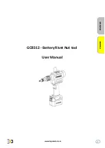
Page 21: ...21 www degometal com GO3312 Battery Rivet Nut tool User Manual FRANCAIS ENGLISH ...

Page 22: ...22 www degometal com ...

Page 23: ... 1 27 Z21009H00 Nosepiece M8 1 4 L41209H00 Adjust sleeve 1 28 L23038H00 Mandrel M4 1 0 L40117H00 Hook 1 29 L23037H00 Mandrel M5 1 9 Z40806H00 Function display 1 30 L23036H00 Mandrel M6 1 20 Z41104H00 Rear cover 1 31 L23035H00 Mandrel M8 1 11 Z4080ZH00 Body GO3312 1 23 Z40509H00 Charger 1 22 Z40828H00 Battery 8 cell 4 0Ah 1 34 F60273H00 Hex screw driver 1 32 L41530H00 Trigger 1 35 L41244H00 Double ...

Page 24: ...tery from the tool Do not use the rivet tool as a striking tool Store the rivet tool in a dry and enclosed place and out of the reach of children Always wear goggles when operating the rivet tool Personal protective equipment such as chemical protective clothing gloves hard hats non slip shoes earplugs and fall arresters are recommended Never block the vents of the motor never insert anything into...

Page 25: ...lled in the tool M5 M6 M8 nosepieces assembly and mandrels are stored in the product box M5 M6 M8 Tool One hex screwdriver SW5 and one SW16 21 double head Nut wrenches are in the product box Hook Folded and embedded to the body Quick charger 100V 240V 50 60 Hz Quick charging battery 14 4 V 4 0 Ah 57 6Wh FRANCAIS ENGLISH ...

Page 26: ...lace sleeve 1 25 Z21011H00 Nosepiece M5 1 9 Z40806H00 Function display 1 26 Z211010H00 Nosepiece M6 1 10 L20127H00 Cross recess pan head screw 1 27 Z21009H00 Nosepiece M8 1 11 Z4080ZH00 Body GO3312 1 28 L23038H00 Mandrel M4 1 12 L40151H00 Cable display 1 29 L23037H00 Mandrel M5 1 13 L40820H00 Cable sensor 1 30 L23036H00 Mandrel M6 1 14 Z40808H00 PCB card 1 31 L23035H00 Mandrel M8 1 15 Z40809H Gear...

Page 27: ...27 www degometal com GO3312 fig B FRANCAIS ENGLISH ...

Page 28: ...1 Fig 2 Hold the replacing sleeve 4 back and unscrew mandrel 1 Fig 3 4 Find out corresponding nose piece hold the replace sleeve back to screw it into the tool and screw the corresponding mandrels with counter nut Fig 3 4 3 2 Adjust the length of Mandrel X Fig 5 Loosen counter nut 2 Rotate the nosepiece 1 based on the length of the rivet nut and adjust the length X of the Mandrel to ensure that al...

Page 29: ... the power is 95 5 3 LED numbers 2 4 6 are on the power is 75 5 2 LED numbers 2 are on the power is 50 5 1 LED numbers 2 is on the power is 25 5 charging is recommended 4 2 Set traction power Set traction power as described below 1 Select traction power by using rapid function setting card enclosed 2 2 Selecting Normal L for M3 M6 Heavy H for M8 M12 Details of operation are described as followed L...

Page 30: ...initial state Press the switch Fig 2 and the release the blue LED indicator L and Speed 2 on display are always on Fig 3 indicating the tool is switched on and the stroke is pre set to 0 2mm Press the switch Fig 4 and then release the blue LED indicator L and speed indicator 4 on the function display are always on indicating the stroke has been successfully switched to 2 4mm As Fig 5 and 6 shown p...

Page 31: ...a rivet nut at the end of mandrel 3 do not tile refer to key points 3 1 and 3 2 fig 5 6 It is recommended to manually screw the rivet nut for about round to make it easier to insert the mandrel 3 Manually push the rivet nut to the nose piece refer to Fig 1 above and the rivet nut is automatically screwed into the mandrel 3 until it fits tightly with the nose piece The screwing process ends automat...

Page 32: ...nsert the hex screwdriver SW5 enclosed into the internal hex at the rear end of the tool and screw to the left carefully if necessary use a wire cutter to clamp the rivet nut to prevent it from moving the rivet nut will be unscrewed Refer to key point 7 of troubleshooting 7 1 the rivet nut cannot be unscrewed 5 3 2 Important note if following mistakes occur The rivet nut is not screwed properly no...

Page 33: ... enclosed place and out of the reach of children Never place a metal object in charging area to avoid circuit If the charger is installed on the wall please ensure the battery will not fall of the charger due to external influences such as vibration This charger should not be used persons with physical or intellectual disabilities or those who are not trained nor have relevant knowledge unless the...

Page 34: ...longer be used and the charging must be terminated 6 4 Battery Insert the battery red led failure indicator cover 9 GO3312 fig A blinks and then goes out indicating the power is on and the tool is on normally Check battery level Pull the trigger and then release fig1 blue led digit indicator on function display fig2 stays on for 3 seconds and then off Check the function display 4 LED indicators ar...

Page 35: ...hould be carried out by approved maintenance workshop or Degometal service center at least once two years If the tool is used frequently maintenance with shorted interval is recommended 7 2 Repair In principle manufacturer should be responsible for warranty If warranty has been expired maintenance should be done only by professionals If rules for installation and adjustment are obeyed or the tool ...

Page 36: ...alified personnel 1 Rotate anticlockwise carefully to loosen rear cover 8 2 Expose the hexagonal hole at the rear end of the tool 3 Insert the hex screwdriver SW5 enclosed into the hexagonal hole rotate anticlockwise carefully to loosen unscrew and replace the rivet nut 4 If necessary use the enclosed double head nut wrench SW 16 21 to rotate the hex screw driver so as to unscrew the rivet nut in ...

Page 37: ...of the tool please ensure the tool is hang securely When the tool is not used or in maintenance and repair please remove the battery When the tool is not use please keep it in package box and store in a dry place and out of the reach of children When using the tool an operator must wear goggles helmet gloves and other necessary personal protective equipment When using the tool please ensure the ve...

Page 38: ...tire tool Wearing parts are not covered by the warranty Manufacturer is not responsible for quality problems caused by improper usage In addition damage or failure caused by storage accident misusing misoperation or unmatched equipment Maximum liability for compensation is not higher than the value of the tool itself not including relevant components In case of any problems please contact your loc...

Page 39: ...39 www degometal com ...

Page 40: ...40 www degometal com Zone Industrielle 1ère Avenue 5ème Rue BP 443 06515 CARROS Cedex1 France Tél 33 0 4 92 08 56 56 Fax 33 0 4 92 08 56 57 sales degometal com www degometal com ...
Reviews: