background image


Content


For your safety .................................................................................................................................................................................. 3 
Technical data and information ........................................................................................................................................................ 3 
Operational conditions ..................................................................................................................................................................... 4 
Terminology ...................................................................................................................................................................................... 4 
Product description ........................................................................................................................................................................... 5 
Instalation, assembly and disassembly of the detector ................................................................................................................... 6 

1. 

Assembly of the detector ...................................................................................................................................................... 6 

2. 

Replacement of the sensor module ...................................................................................................................................... 6 

3. 

Replacement of the battery .................................................................................................................................................. 6 

4. 

Connecting the detector via current loop to the controler DEGA UPA II/DEGA UPA III ....................................................... 7 

5. 

Connecting the sensor via RS485 to the controller DEGA UKAIII/DEGA UPA III/DEGA UDA III ............................................ 7 

6. 

Installation of wiring for RS485 ............................................................................................................................................. 7 

7. 

Setting the RS485 adress of the detector ............................................................................................................................. 7 

8. 

Terminating resistor .............................................................................................................................................................. 7 

9. 

Communication protocol switch DEGA/MODBUS ................................................................................................................ 8 

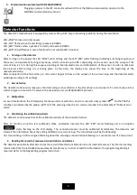
Detector functions ............................................................................................................................................................................ 8 

1. 

Turning on the detector ........................................................................................................................................................ 8 

2. 

Gas detection ........................................................................................................................................................................ 8 

3. 

Malfunction ........................................................................................................................................................................... 8 

4. 

Monitoring the calibration periods ....................................................................................................................................... 8 

5. 

Reading the record of measured concentrations and alarms .............................................................................................. 8 

Detector controls .............................................................................................................................................................................. 9 

1. 

History menu „HIST“ ........................................................................................................................................................... 10 

2. 

Information menu „INF“ ..................................................................................................................................................... 10 

3. 

Settings menu „SET“ ........................................................................................................................................................... 11 

4. 

Test menu „TEST“ ............................................................................................................................................................... 13 

Operation, maintenance, inspection and service of the detector .................................................................................................. 14 

1. 

Usage limits ......................................................................................................................................................................... 14 

2. 

Operation ............................................................................................................................................................................ 14 

3. 

Operation/Maintenance ..................................................................................................................................................... 14 

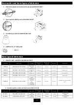
Accessories and basic types of detectors ....................................................................................................................................... 15 

1. 

Calibration adapter/connection to the gas pump DEGA GAS INLET .................................................................................. 15 

2. 

Cover against splashing water DEGA WATER CAP .............................................................................................................. 15 

3. 

Funnel for gas collection DEGA COLLECT CAP .................................................................................................................... 15 

4. 

Additional Ex „d“ cable gland .............................................................................................................................................. 15 

Basic type of detectors ................................................................................................................................................................... 15 

1. 

Detectors with a catalytic sensor NSx-CL III LCD ................................................................................................................. 15 

2. 

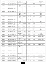
Detectors with an electrochemical sensor NSx-EL III LCD .................................................................................................. 15 

3. 

Detectors with an infrared sensor NSx-IL III LCD ................................................................................................................ 17 

4. 

Detectors with a semiconductor sensor NSx-SL III LCD ...................................................................................................... 18 

5. 

Detectors with a PID sensor NSx-PL III LCDPID ................................................................................................................... 18 

Add-on modules .............................................................................................................................................................................. 19 
Attachments .................................................................................................................................................................................... 19 

1. 

Chart for setting the detector address ............................................................................................................................... 19 

2. 

Conversion between volumetric concentration and lower explosion limit of methane .................................................... 19 

3. 

Table of error codes ............................................................................................................................................................ 19 

4. 

Signalization transmitted by the current loop 4-20 mA ..................................................................................................... 20 

5. 

Package content .................................................................................................................................................................. 20 

General warranty terms and conditions ......................................................................................................................................... 21


Summary of Contents for NS CL III LCD Series

Page 1: ...in any form without the prior permission of DEGA CZ s r o is prohibited DEGA CZ s r o reserves the right to alter the specifications of the hardware and software described in this manual at any time and without prior notice DEGA CZ s r o bears no liable for any damage resulting from use of this device ...

Page 2: ...ation menu INF 10 3 Settings menu SET 11 4 Test menu TEST 13 Operation maintenance inspection and service of the detector 14 1 Usage limits 14 2 Operation 14 3 Operation Maintenance 14 Accessories and basic types of detectors 15 1 Calibration adapter connection to the gas pump DEGA GAS INLET 15 2 Cover against splashing water DEGA WATER CAP 15 3 Funnel for gas collection DEGA COLLECT CAP 15 4 Addi...

Page 3: ...rotection Use the detector only with the appropriate certified DEGA products The device is certified as functionally and technically qualified only with original DEGA accessories In case of using the device with any other products the manufacturer is not liable for any damages that may occur Undertake regular functional checks and calibrations of the detector Perform regular CALIBRATION setting th...

Page 4: ...H Air pressure 80 120 kPa Flow of ambient air max 2 m s flow directly to the sensor in not allowed Protection level with a cover IP 54 with a DEGA WATER CAP IP 66 cover Location BE3N2 explosive atmoshpheres zone 1 2 G Terminology The marking system for detector DEGA NSx yL III LCD Gas detector DEGA NSx yL III LCD Series of detectors in potentially explosive atmospheres Type of detected gas Sensor ...

Page 5: ...ce instantaneous readings operate continuously and are commonly used as detectors for gas chromatography or as hand held portable instruments Hand held battery operated versions are widely used in military industrial and confined working facilities for health and safety Their primary use is for monitoring possible worker exposure to volatile organic compounds VOCs such as solvents fuels degreasers...

Page 6: ...ternal hexagon of 5 mm b Disconnect the LCD from the motherboard c Mount the detector on a flat surface using four 6 mm dowels to a height above the floor according to the specification of the detected substance with the gas inlet facing downwards d Pass the cable through the gland e Connect the cabling to the detector terminal board according to the chapters connection of the detector to control ...

Page 7: ...xternal influences 7 Setting the RS485 adress of the detector Each detector must have a unique adress within the entire bus otherwise there will be communication collisions and malfunctions The detector adress can either be set internally using the DegaConfig program or using the DIP switch on the PCB If the position 6 labeled ADD is in the ON position then the adress according to the setting of p...

Page 8: ...s detection The detector continuously measures the detected gas concentration in the atmoshpere and converts it s current value into a 4 20 mA signal or transmits it s value to the evaluation unit via DEGA MOBUS protocol 3 Malfunction In case of malfunction the LCD displays the measured concentration an error code and a key symbol On the PCB this condition is indicated by the yellow ERR LED The me...

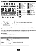
Page 9: ...ls Alarm indication BACK move backwards in the menu reducing the value FRONT move forwards in the menu increasing the value ENTER confirm enter the menu Placing a magnet into the indent for 5 s activates the magnetic control which is displayed by the icon on the LCD Reaching level 4 alarm with catalytic and semiconductor sensors causes a ratchet phenomenon where even after recovery from gas leak t...

Page 10: ...e past 8 hours Return to History menu Highest concentration in the past 12 hours Displays the highest measured concentration and alarm for the past 12 hours Return to History menu Highest concentration in the past 24 hours Displays the highest measured concentration and alarm for the past 24 hours Return to History menu Highest concentration stored in the memory Displays the highest measured conce...

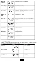
Page 11: ... mA current Alarm level 1 Displays alarm level 1 Alarm level 2 Displays alarm level 2 Alarm level 3 Displays alarm level 3 Alarm level 4 Displays alarm level 4 3 Settings menu SET Protected by password 0004 By enetering a wrong password the detector returns to measurement mode The password can be changed in the menu SET PSWD Menu Display Description Calibration Sensor calibration Setting the alarm...

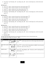
Page 12: ...restart Setting the alarms a Using select the concentration for alarm 1 Confirm b Using select the concentration for alarm 2 Confirm c Using select the concentration for alarm 3 Confirm d Using select the concentration for alarm 4 Confirm e Using switch between YES save settings or NO return to the Settings menu Confirm the selected option Setting the range of the 20 mA current loop a Using select...

Page 13: ...ttings nebo NO return to the Settings menu Confirm the selected option Setting the time a Using select a number in thousands Save the selected number b Using select a number in hundreds Save the selected number c Using select a number in tens Save the selected number d Using select a number in units Save the selected number e Using switch between YES save settings nebo NO return to the Settings me...

Page 14: ...f the measured value e photoionization sensors the UV lamp or sensor must be replaced regularly its clogging may cause loss of signal 2 Operation To maintain proper operation of the detector it is neccesery to respect the fact that the presence of certain concentrations of gases or vapors other than those for which the sensor is set can cause an alarm even if the concentration of the gas does not ...

Page 15: ... 0 100 LEL 0 20 LEL 0 1 LEL Butane 0 32 40100160 DEGA NSH CL 100 III LCD RE Hydrogen H2 0 100 LEL 0 20 LEL 0 1 LEL Hydrogen 0 8 40100157 DEGA NSB CL 100 III LCD RE Gasoline vapors 0 100 LEL 0 20 LEL 0 1 LEL Hexane 0 18 40100158 DEGA NSHC CL 100 III LCD RE Other flammable and combustible gases and vapors according to the selectivity of the sensor 0 100 LEL 0 20 LEL 0 1 LEL According to the selectiv...

Page 16: ... chloride HCl 0 200 ppm 0 200 ppm 0 1 ppm Hydrogen chloride 25 ppm 40100125 DEGA NSH2S EL 50 III LCD Hydrogen sulfide H2S 0 50 ppm 0 15 ppm 0 1 ppm Hydrogen sulfide 25 ppm 40100119 DEGA NSH2S EL 500 III LCD Hydrogen sulfide H2S 0 500 ppm 0 500 ppm 1 ppm Hydrogen sulfide 500 ppm 40100121 DEGA NSH2S EL 100 III LCD Hydrogen sulfide H2S 0 100 ppm 0 100 ppm 0 1 ppm Hydrogen sulfide 25 ppm 40100118 DEGA...

Page 17: ...SPH3 EL 20 III LCD Phosphine PH3 0 20 ppm 0 20 ppm 0 01 ppm Hydrogen sulfide 25 ppm 40100145 DEGA NSPH3 EL 200 III LCD Phosphine PH3 0 200 ppm 0 200 ppm 0 1 ppm Hydrogen sulfide 25 ppm 40100146 DEGA NSPH3 EL 2000 III LCD Phosphine PH3 0 2000 ppm 0 2000 ppm 1 ppm Hydrogen sulfide 250 ppm 40100147 DEGA NSSIH4 EL 50 III LCD Silane SiH4 0 50 ppm 0 5 ppm 0 1 ppm Hydrogen sulfide 25 ppm 40100149 DEGA NS...

Page 18: ...exane Petrol 0 100 LEL 0 20 LEL 0 1 Hexane 20 LEL 40100175 DEGA NSHC IL 100 III LCD RE Nitrous oxide N2O 0 1 LEL 0 0 5 LEL 0 01 Nitrous oxide 0 5 LEL 4 Detectors with a semiconductor sensor NSx SL III LCD Product code Detector type Detected gas Measurement range Measurement of current loop 4 20mA Resolution Calibration gas 40100163 DEGA NSY SL 100 III LCD RE Acetylene C2H2 0 100 LEL 0 20 LEL 0 1 2...

Page 19: ...N OFF OFF OFF ON 18 OFF ON OFF OFF ON 19 ON ON OFF OFF ON 20 OFF OFF ON OFF ON 21 ON OFF ON OFF ON 22 OFF ON ON OFF ON 23 ON ON ON OFF ON 24 OFF OFF OFF ON ON 25 ON OFF OFF ON ON 26 OFF ON OFF ON ON 27 ON ON OFF ON ON 28 OFF OFF ON ON ON 29 ON OFF ON ON ON 30 OFF ON ON ON ON 31 ON ON ON ON ON 32 OFF OFF OFF OFF ON 3 Table of error codes code cause solution 1 Sensor is not present EEPROM is not com...

Page 20: ...erry 129 The measured value exceeds the range of 10 If the error persists contact the manufacturer 130 The result of the AD covertion is out of range Contact the manufacturer 4 Signalization transmitted by the current loop 4 20 mA Measurement The measure concentration is directly proportional to 4 20 mA current output Exceeding the range of measured concentrations Current output ranges from 20 22 ...

Page 21: ...ct shall be replaced 616 paragraph 4 of the Commercial Code 6 The buyer who exercises the right of warranty repair is not entitled to the return of the parts that have been replaced 7 The warranty period can be extended for up to 48 months and its validity can be extended beyond the standard length on the basis of the conclusion of an individual warranty contract Further information may be obtaine...

Reviews: