


TEX-BAR-MAN-15V05 (0903)
Copyright © 2015 Defi ne Instruments
20
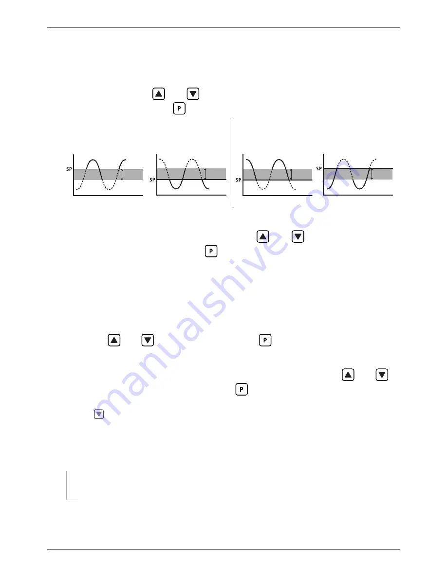
ABOVE
: Relay turns on above the setpoint value and off below it.
BELW
: Relay turns on below
the setpoint value and off above it.
D
_ _ _ SETPOINT TYPE
scrolls across the display and toggles with the current
selection. Using the
and
buttons, select either
ALRM
(alarm) or
CNTRL
(control), and then press
.
ALRM - SETPOINT VALUE
controls setpoint
activation point.
HYSTERESIS VALUE
con-
trols setpoint deactivation point.
CNTRL - SETPOINT VALUE
controls setpoint
deactivation point.
HYSTERESIS VALUE
con-
trols setpoint reactivation point.
Energised Above
Hysteresis
band
Energised Below
Hysteresis
band
Energised Above
Hysteresis
band
Energised Below
Hysteresis
band
E
_ _ _ HYSTERESIS VALUE
scrolls across the display and toggles with the hyster-
esis value for the selected setpoint. Use the
and
buttons to adjust this
value if required, and then press
.
The
HYSTERESIS VALUE
defi nes the separation band between setpoint activation and deacti-
vation, and will operate as per the
SETPOINT TYPE
setting selected in 7.2D.
F
_ _ _ MAKE DELAY
scrolls across the display and toggles with the current make
delay time for the selected setpoint. This is the time delay between setpoint ac-
tivation, and when the relay turns on. Adjust this value in 0.1 second increments
using the
and
buttons, and then press
.
G
_ _ _ OPEN ACCESS TO SP VALUE
scrolls across the display and toggles with the
open access permission setting for the selected setpoint. Use the
and
to
select either
NO
or
YES
, and then press
.
When enabled, this option allows the selected setpoint's value to be edited directly aft er press-
ing the
button, without needing to enter a PIN number or go through all of the other op-
tions. Each setpoint can individually have this option enabled or disabled. See Section 8.
H
The step that you proceed to now will depend on which setpoint you are editing
(selected in 7.2A):
If you are currently editing
SP 1
, skip to 7.2J now.
If you are currently editing
SP 2–4
, continue to 7.2I now.


