


5
Input,
230V,
50 Hz
10 A
-power
cord
(plug)
+24
0
0-10
CO2/%RH1
+24
0
0-10
CO2/%RH2
0-10
+24
0
0-10 +24
0
+24
0
WINTER
YHT
SUMMER
NC
YHT
NO
G
+
G
0
O
U
T
1
CO2
sensor
0
0
-1
0V
COOKER HOOD
0-10v voltage signal
0
0
-1
0V
PC EC
PG EC
230V,
50 Hz
10 A
KTS
NO
COM
NC
open
closed
cooling
coil
actuator
DC 24 V
0-10v
A
L
A
R
M
NC
YH
T
NO
M
max.
8A
250V
L
N
230 V
max.
8A
250V
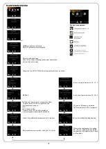
NO
- machine running
NC
- machine off
- alarm temperatures
- alarm sensors
- over-temperature alarm
- machine in standby mode
NC
YH
T
NO
max.
8A
250V
VAK
NO NC
GENERAL ALARM
A
L
A
R
M
HUMIDITY
TRANSMITTER
VS+ GND
RH
overpressure
setpoint 0
tip of the data in
M
O
D
B
U
S
A/D+
B/D-
0
MODBUS
O O O
O O O
O O O
ON OFF BIAS B
ON OFF Term
ON OFF BIAS A
ALARM INDICATION
AND OPERATING
POTENTIAL FREE CONTACT
INFORMATION MACHINE
OR CONTROL OF
SPRING RETURN DAMPER
MOTOR
P
u
ls
e
s
w
it
c
h
s
w
it
c
h
P
u
ls
e
s
w
it
c
h
P
re
su
re
sw
itc
h
e
s
switch
switch
boosting
setpoint 0
tip of the data in
COOKER HOOD
boosting information
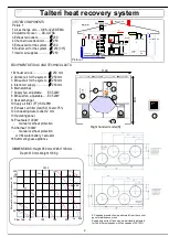
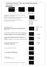
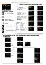
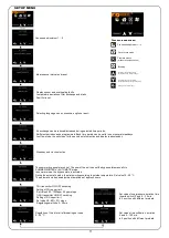
Operator panel
Spring return damper motor connection
The damper motor closes
- the machine stopped
- the machine in standby mode
- the machine alarm
al
ar
m
su
m
m
e
r
b
yp
a
ss
sensor 1
sensor 2
overpressure/
extended
time
boosting
out-of house/
remote
filter
cooling
water radiator
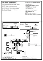
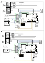
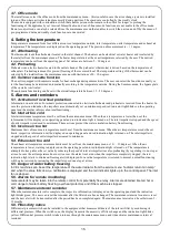
The fan speed of Talteri ventilation unit can be controlled with
Ultra PC EG, PG EC, DS-600 EC and DSA-900 EC cooker hood
or 0-10 V voltage signal from Control panel.
The voltage signal connected to
CO2/%RH1
terminal.
Sensor 1(EXT) can be operated through maintenance menu
of the operating panel.
The boosting of Talteri ventilation unit can controlled with
Ultra KTS cooker hood.
There is a control panel and when the closing damper of the cooker hood
is open the fan speed is enhanced.
Maintenance menu is used to set boost 0, there can be operated the
guantity of boost too.
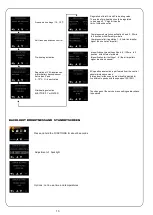
ELECTRICAL CONNECTIONS
Electrical connections must be done following the installation manual
and wiring diagram.
ELECTRICAL CONNECTIONS CAN BE DONE ONLY BY
AN ENTREPRENEUR WITH RESPECTIVE INSTALLATION RIGHTS.
The electrical connection box opens from the bottom of the machine
by removing the fastering screws . The electrical connection box is
taken out by pulling it up to its limit.
The machine has a plug connection.
The control panel is connected to the control card with a modular connector.
The following can be connected as accessories:
- Carbon dioxide transmitter;
- Humidity transmitter;
- Separate Overload or Extended Period switch
(pulse switch);
- Separate Boost switch (pulse switch);
or setting off as pre-data (for instance,
sauna oven, stove hood);
- Remote control or out-of-home switches
(pre-data);
- Differential pressure switches for filters;
- External speed control 0-10V.
- Modbus.
The functions can be operated through
maintenance – and setup menus of the operating panel.
COM
NC
COM
NC
contact tip information extract fan
max. 2A 250V
contact tip information supply fan
max. 2A 250V
VAK
VAK


