background image

4.4 Test 

modes 

IDM 50 modem provides on-line test and control functions, such as remote feedback looping 
and the transmission of test sequences, thus making possible to measure in-channel signal level 
and count bit errors. This possibilities considerably improve commissioning and maintenance 
of telecommunications links. 

Tests may be initiated when modem is in command mode, by sending test command string 
from the PC or terminal. There are 3 types of test commands: INTERNAL, LOCAL and 
REMOTE. Generic test command format is 

AT&TSTx

, where 

x

 represent number of test. 

Before entering test mode modem return “ENTERING TEST MODE x” where x represents 
number of test.  


INTERNAL TEST

 – Allows validating the correct operation or not of the DSP and Codec 

which generates, decodes and processes signals exchanged with the analog line.   


AT&TST0

 Self 

test

 – internal test of DSP and Codec. No line signal is generated nor 

received during this test. After less than one second modem automatically 
return to command mode and returns “OK” message. 


LOCAL TESTS

 – Enable validation of entire generation, transmission and reception chain of 

modem. In this tests modem generate and transmit specific test signal and at the same time 
performs receiving function with receive signal level measuring. Measurements are of narrow-
band in-channel type. During tests PWR led blinks fast (100ms / 100ms cycle), DSR and CTS 
signals at RS-232 interface are active, DCD led and DCD RS-232 signal indicate receive signal 
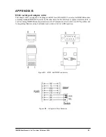
strength but no RxD signal at RS-232 is received. External loop-back wiring may be attached at 
DB15 connector to route transmitted test signal back to receiver. Test 1 use 800Hz test signal 
while tests 2, 3, 4 and 5 are performed on pre-programmed TX and RX channels with pre-
assigned TX and RX levels. 

Exit from this tests, and return to command mode may be accomplished by sending any 
character from terminal or PC to modem. Modem returns values of received level in dB units, 
and duration of test in seconds. 


AT&TST1


800Hz generation and detection

 – generation, transmission and reception 

chain with 800Hz test signal.  

AT&TST2

 Sequence 

F-

  - generation, transmission and detection of lower frequency of 

the channel. Valid only in FSK mode. 

AT&TST3

 Sequence 

F+

  - generation, transmission and detection of upper frequency of 

the channel. Valid only in FSK mode. 

AT&TST4

 Sequence 

F+/F-

  - generation, transmission and detection of both significant 

frequencies of channel in alternate and symmetrical sequence. Valid only in 
FSK mode. 

AT&TST5

 Received 

Level

  - measurement of reception level in dB but without generated 

and transmitted signal. 


Example:


AT&TST3 
 
ENTER TEST MODE 3 
 
EXIT TEST MODE 
 
TEST STATUS: OK 
RX LEVEL:   -08dBm 
ELAPSED SEC: 00000007 


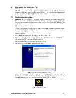
IDM50B User Manual v1.2n, Rev. date: 24 februar, 2009 


14


Summary of Contents for IDM 50B

Page 1: ...DECODE Multi standard modem IDM 50B User Manual v1 2n http www decode co yu ...

Page 2: ...nts 32 bit DSP technology thus offering high service flexibility through programmable features Modem configuration is performed via Hayes AT commands on separate DIAG serial port available at front panel AT commands may be initiated from any asynchronous terminal application using RS 232 communication interface Additionally for easy firmware upgrade a bootstrap loader is provided using the same DI...

Page 3: ... LED blinks slowly 1sec 1sec cycle when modem is remotely brought to some of the test modes TXD Transmit LED indicates data transmitted on TXD pin of RS 232 interface RTS Request to Send LED indicates state of RTS pin of RS 232 interface RXD Receive LED indicates data received on RXD pin of RS 232 interface DCD Data Carrier Detect LED indicates the presence of in channel carrier with level higher ...

Page 4: ...s the interface between the modem and remote terminal unit or data processing equipment in data mode The following table gives the allocation and function of each pin PIN ABB FUNCTION DIRECTION DTE DCE 1 DCD Data Carrier Detect 2 RD Received Data 3 TD Transmitted Data 4 DTR Data Terminal Ready 5 SG Signal Ground 6 DSR Data Set Ready 7 RTS Request To Send 8 CTS Clear To Send 9 RI Ring Indicator IDM...

Page 5: ...rent firmware version Figure below depicts analog line interface Figure 4 Analog line interface 2 2 4 Power Power Supply Power supply connector is a 2 position screw plug type for 2 2 5 2 mm wire used for connecting the modem to a DC power supply Polarity is irrelevant Maximum consumption is 3VA Table of possible voltage options are shown below Option Nominal Voltage V Voltage Range V DC DC conver...

Page 6: ...0 JP403 1 2 JP405 JP406 1 2 4 wire FSK and V 29 mode Z input 600Ω Z output 600Ω JP401 JP402 2 3 JP405 1 2 4 wire FSK MUX1 mode Z input 10kΩ Z output 600Ω JP401 JP402 JP406 2 3 JP402 1 2 Z input 600Ω Z output 10kΩ JP401 JP405 JP406 2 3 4 wire FSK MUX2 mode Z input 10kΩ Z output 10kΩ JP401 JP402 JP405 JP406 2 3 JP405 1 2 2 wire FSK MUX1 mode Z 600Ω JP401 JP402 JP406 2 3 Input Output Impedance JP401 ...

Page 7: ...and DEF2 to connector JP412 ON JP411 OFF Fail relay signal presence on connector JP411 JP412 Do not proceed fail relay signals DEF1 and DEF2 to connector JP412 OFF JP408 ON Proceed the alternate squelch data signals SQ and SQ to connector JP410 ON JP408 OFF Squelch data signal presence on connector JP408 JP410 Do not proceed squelch data signals SQ and SQ to connector JP410 OFF Enabled by switch o...

Page 8: ...ssage Entered command is accepted only if previous AT command is executed and acknowledged with corresponding message Advice Since modem doesn t support character echoing in command mode it is advised to activate local echo in terminal application Telix HyperTerminal etc used for AT setting Local echo will help to insure which characters were typed and sent to modem 4 2 Entering Command Mode By de...

Page 9: ...ts Cegelec 600Bd 60x channels for data transmission Valid range for x is 1 3 corresponding to channels 601 to 603 AT TC40x y Sets CCITT R 38A 200 300Bd channels for data transmission Valid range for x is 1 7 corresponding to channels 401 to 407 valid range for y is 1 2 corresponding to 200 300Bd channels baud rate respectively AT TC30x Sets CCITT R 38B 200Bd channels for data transmission Valid ra...

Page 10: ...n FSK modes When set to 0 then normal FSK frequencies order are set and F corresponds to data line SPACE condition and F corresponds to data line MARK condition When set to 1 then reverse FSK frequencies order are set and F corresponds to data line MARK condition and F corresponds to data line SPACE condition If invalid range is entered modem responds with ERROR message otherwise responds with OK ...

Page 11: ...ts RTS CTS delay at 50ms Modem responds with OK message Fail If DCD Off AT DCDx Turns on off Fail if DCD off option For x 0 modem FAIL relay doesn t react on DCD changes For x 1 FAIL relay is switched on when DCD 0 CD led on the modem front side follows DCD changes PTT When TX On AT PTTx Turns on off PTT When TX On option For x 0 modem PTT relay doesn t react on carrier On Off changes For x 1 PTT ...

Page 12: ...tween 5 and 9 useful bits enclosed with 1 start and 1 stop bit The parity bit and additional stop bit is considered as a data bit and will be transmitted without processing therefore for example transmission and reception of 9N1 format is possible with FSK modulations with 8E1 or 8O1 settings Example AT CF8N1 command line sets format 1 start 8 data 1 stop bit Modem responds with OK message Display...

Page 13: ...onfiguration command is not executed before switching off the modem Display Modem Info ATI Displays full modem info manufacturer model type firmware version and date in following format DECODE IDM 50B LS vx x dd mm yy IDM50B User Manual v1 2n Rev date 24 februar 2009 13 ...

Page 14: ...surements are of narrow band in channel type During tests PWR led blinks fast 100ms 100ms cycle DSR and CTS signals at RS 232 interface are active DCD led and DCD RS 232 signal indicate receive signal strength but no RxD signal at RS 232 is received External loop back wiring may be attached at DB15 connector to route transmitted test signal back to receiver Test 1 use 800Hz test signal while tests...

Page 15: ...tialized from non volatile memory There are 4 remote test commands All of them first issue remote loop back command to remote modem addressed with specified remote address If remote loop may not be establish error test status is returned When remote loop are established and test is in progress return to command mode may be accomplished by sending any character from terminal or PC to modem Also tes...

Page 16: ... This state is indicated by slow PWR led blink 1sec 1sec cycle Modem performs the same task as it have received remote loopback pattern Modem turns carrier on at transmit port and expect carrier at receive port If there is carrier signal present at receive port modem remain in loopback mode as long as carrier exists To exit from this mode unconditionaly just press RST switch at the front panel IDM...

Page 17: ...st one RS232C serial port available Bootloader procedure may be started without modem power turn off Follow steps below 1 If you already have installed C2000Prog on your PC skip steps 2 and 3 2 Unzip bootloader program C2oooProg_v1 2d zip on your PC It may be found on IDM50B support CD or may be downloaded at no charge from http www code skin com downloads C2oooProg_v1 2d zip 3 Start instalation S...

Page 18: ...eri 4 COM1 is selected in this example Select Target 2811_API2 10_30MHz 9 Skip Code Security Keys All labels mu FFFF value Warning Do not change these values or modem DSP may be permanently locked after uploading of new firmware Skip Flash Sector to be Erased 11 Tick Smart Sector Selection 12 Click at Program command dialog appeared Select and open new firmware file File format is Intel hex with h...

Page 19: ... Rack frame 1U 84TE Front view A F Figure A1b Rack frame 1U 84TE Rear view igure A1c Rack frame 1U 84TE Side view F 172 5 175 igure A1d Rack 1U 28TE Front plate view F igure A1e Rack 1U 28TE Rear view F IDM50B User Manual v1 2n Rev date 24 februar 2009 19 ...

Page 20: ...ST SET DECODE PWR TXD RTS RXD DCD RST SET DECODE PWR TXD RTS RXD DCD RST SET DECODE PWR TXD RTS RXD DCD RST SET DECODE PWR TXD RTS RXD DCD RST SET DECODE PWR TXD RTS RXD DCD RST SET DECODE PWR TXD RTS RXD DCD RST SET DECODE PWR TXD RTS RXD DCD RST SET DECODE PWR TXD RTS RXD DCD RST SET DECODE 465 57 1 Figure A2b Rack frame 3U 84TE Rear view 175 172 5 Figures A2 c Rack frame 3U 84TE side view d Rac...

Page 21: ...3 IDM 50B Desktop Figure A3a Front view Figure A3b Rear view RS 232C Line DECODE data communications www decode co yu Power Figure A3c Top view 168 0 IDM50B User Manual v1 2n Rev date 24 februar 2009 21 ...

Page 22: ...DCE pinout on the other side of cable DIAG port equiped with this cable is used for setting IDM50B modem parameters with AT commands when switch is in RUN position and for upgrading firmware using bootloader mode when switch is in BSL position Figure B1 RJ45 and DB9F connectors Figure B2 Adapter cable schematics IDM50B User Manual v1 2n Rev date 24 februar 2009 22 ...

Page 23: ...202 660 720 780 CH203 900 960 1020 CH204 1140 1200 1260 CH205 1380 1440 1500 CH206 1620 1680 1740 CH207 1860 1920 1980 CH208 2100 2160 2220 CH209 2340 2400 2460 CH210 2580 2640 2700 CH211 2820 2880 2940 CH212 3060 3120 3180 CH101 390 420 450 CH102 510 540 570 CH103 630 660 690 CH104 750 780 810 CH105 870 900 930 CH106 990 1020 1050 CH107 1110 1140 1170 CH108 1230 1260 1290 CH109 1350 1380 1410 CH1...

Reviews: