background image

SI-3C


U

ser
’s M
anual

14

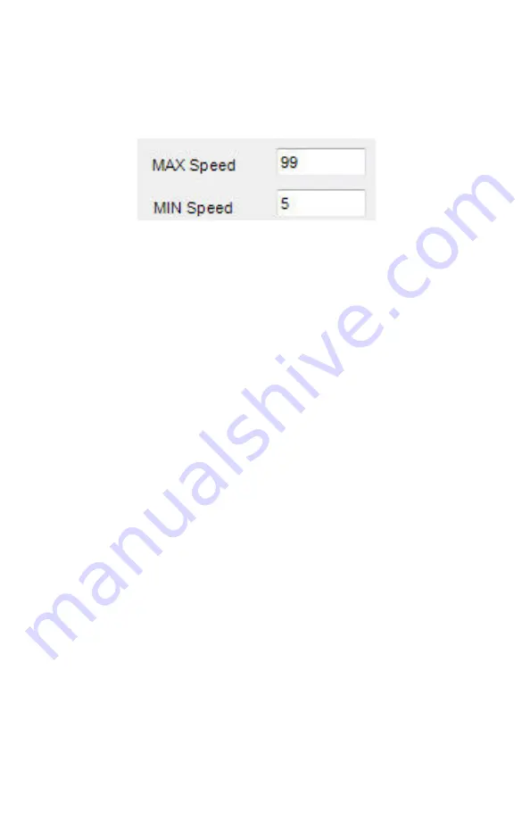
The speed range can be adjusted within those ranges by changing 
the speed readings that appear in the 

"MAX Speed"

 and 

"MIN Speed"


windows (See Figure 4 .4 .3b) . No vehicles will be reported outside 
the minimum and maximum configured speeds

Figure 4.4.3b

Set the speed range you want to use

As an example,  when 

"mph"

 is selected the minimum and 

maximum speeds that can be processed are 1 to 301 mph 
respectively . However, if the SI-3C™ is going to be used in an 
application where any speed above 90 mph is to be ignored, then 
the 

"MAX Speed"

 window can be changed to 90 and no speed 

above 90 will then be processed . Likewise, if the SI-3C™ is to be 
used where no speeds below 30 mph need to be considered then 
setting the 

"MIN Speed"

 to 30 will cause the SI-3C™ to not report 

any speeds below 30 mph .

4.4.4  Target Report

The "

Target Report"

 has four selections and allows you to set the 

direction reporting of the SI-3C™ . It is recommended that the user 
start with the "All" selection when first setting up the SI-3C™ .


All

 - Tracks the strongest overall target signal regardless of 

direction .

• 

Approach and Recede

 - Tracks the strongest true directional 

target coming towards or going away from the SI-3C™ . This 
mode contains directional filtering that will filter out any signal 
that doesn't have a good directional signal .

• 

Approach

 - Tracks the strongest true directional target coming 

towards the SI-3C™ . This mode contains directional filtering 
that will filter out any signal that does not have a good 
directional signal .

Summary of Contents for SI-3C

Page 1: ...User s Manual Rev 5 14 19 SI 3C System Interface 3 Compact Low Profile ...

Page 2: ... Screen 15 4 4 1 Serial Number 15 4 4 2 Unit ID 15 4 4 3 Measurement 15 4 4 4 Target Report 16 4 4 5 Target Select 17 4 4 6 Cosine Horizontal and Cosine Vertical 17 4 4 7 Hold Time 18 4 4 8 Update Rate 18 4 4 9 Sensitivity 18 4 4 10 Baud Rate 20 4 4 11 Serial Protocol 20 4 5 Loading New Firmware Configuring the SI 3C 20 4 6 Configurtion Notes 23 4 7 SI 3C Command Set 24 5 Performance Tips 28 5 1 H...

Page 3: ...32 7 Care Cleaning and Storage 33 8 Specifications 33 8 1 Antenna Parameters 33 8 2 Environment 33 8 3 Speed Range Parameters 33 8 4 Power Consumption 33 9 Legal Requirements 34 9 1 Documents 34 9 2 FCC Statement 35 9 3 Conditions 35 9 4 Installer Note 35 9 5 End User Note 35 9 6 Industry Canada 35 10 Frequently Asked Questions FAQ 36 11 Warranty 36 12 Service Return Procedure 37 13 How To Order A...

Page 4: ...s manual before using the SI 3C so you can maximize the benefits of this sophisticated radar device We believe you will be pleasantly surprised by the features and advantages If you are as pleased with its performance as we think you will be ask your Decatur sales representative about other Decatur products including the Genesis line of radars the Onsite line of speed trailers dollies pole signs a...

Page 5: ...1 Safety Information All service needs should be referred back to the manufacturer WARNINGS Do not over voltage the radar it can damage the unit The SI 3C is designed to operate off of conventional 12 VDC 9 VDC to 24 VDC from the serial cable Important Warnings Disassembly of the SI 3C automatically voids any warranty still in effect There are no user serviceable parts inside Do not expose the SI ...

Page 6: ... pictures to document any damage Notify the freight company immediately of any damage preferably while the driver is present Record the damage on the bill of lading and keep a record of the problems or damage The package should include the following pictured items along with this User s Manual SI 3C Programming Software S900 34 Tuning Fork S769 78613 0 Serial cable ...

Page 7: ...available that allows you to display speed information on your computer and record that information to a text file for analysis 3 2 Connecting the Serial Cable The SI 3C operates off of 12VDC and comes with a cable that has two connectors The circular connector plugs into the SI 3C and the DB 9 serial connector shown in Figure 3 2 is used for powering and communicating with the SI 3C When connecti...

Page 8: ...e that is connected to 12 VDC and a black wire that is connected to ground A regulated power supply can be used to supply the 12 VDC Once the programming software is installed on the computer then the SI 3C can be accessed and parameters changed to meet your application Refer to Chapter 4 for programming information Figure 3 3 S769 127 0 Optional Programming Cable 3 4 Mounting Configuration The SI...

Page 9: ...drive S785 1 0 12V power supply 4 2 Setup 1 Connect the SI 3C to the programming cable using the end of the cable that has the red and black wire coming out of it 2 Connect the red wire to the positive 12 VDC of the power supply and connect the black wire to the negative ground side of the power supply Do not turn the power supply on 3 Connect the other end of the programming cable to the serial p...

Page 10: ... port you can find what port has been assigned by checking Device Manager Ports on your computer The port assignment will appear as USB Serial Port Note the port assignment The example in Figure 4 3b shows that Port 4 has been assigned Your port assignment may be different and the port assignment can change the next time the USB to Serial adapter is plugged in to the computer Figure 4 3b Device Ma...

Page 11: ...the USB to Serial adapter use the port shown in Device Manager Ports Once the correct port is known the Device Manager Computer Management screens can be closed Figure 4 3c Comm port selection 4 Once the COM port has been selected left click on the Open Port button A COM port OPEN message will be displayed indicating that the COM port is now active See Figure 4 3d Figure 4 3d Press the Open Port b...

Page 12: ...ng up the SI 3C Configuration Items dialog box Figure 4 3f Figure 4 3f Configuration Items screen 8 Select new options for programming as desired An explanation of the settings is described in Section 4 4 9 Once new options have been selected press the OK button The Configure program will upload the new settings and the SI 3C will start ...

Page 13: ...r hour Select mph Kilometers per hour Select km h Meters per second Select m s Feet per second Select fps The maximum and minimum speed range for each of the speed formats will be displayed in the Max speed for this unit is and the Min speed for this unit is windows The speed ranges for the various selections are For mph the speed range is 1 330 mph pre set at 5 99 For km h the speed range is 2 48...

Page 14: ...used where no speeds below 30 mph need to be considered then setting the MIN Speed to 30 will cause the SI 3C to not report any speeds below 30 mph 4 4 4 Target Report The Target Report has four selections and allows you to set the direction reporting of the SI 3C It is recommended that the user start with the All selection when first setting up the SI 3C All Tracks the strongest overall target si...

Page 15: ... SI 3C configuration Figure 4 4 5 Target Select 4 4 6 Cosine Horizontal and Cosine Vertical For bridge type installations where the SI 3C is over the traffic and pointing slightly down the vertical angle can be entered here to ensure that the SI 3C calculates the correct vehicle speeds For installations where the SI 3C is at a significant angle from the road the horizontal angle can also be config...

Page 16: ...econd or as high as 10 seconds The Update Rate and the amount of serial port activity do not affect the measurement accuracy of the SI 3C The default rate is 1 Second Figure 4 4 8 Update Rate 4 4 9 Sensitivity The SI 3C has a sensitivity range of 1 10 and is shipped with the range setting at the 10 maximum See Figure 4 4 9 The sensitivity can be decreased for closer range if needed When changing t...

Page 17: ...Setting Range feet 1 350 2 575 3 800 4 950 5 1300 6 1700 7 1875 8 2400 9 2800 10 3000 Figure 4 4 9 The distances will vary based on location body of the car and alignment of the antenna It is normal for the range to vary by 10 on identical cars Figure 4 4 9 Sensitivity Setting ...

Page 18: ... within the square brackets it is the decimal point Any zeros are sent as described and do not change with a vehicle s speed The cr signifies the end of the outgoing message Figure 4 4 11 Serial Protocol Once new options have been selected press the OK button The Configure program will save the new settings into memory and the SI 3C will start each time with these new settings until you change the...

Page 19: ...C Configuration Program is designed automatically recognize the USB port However if it does not you can select the port yourself For instructions on determining the correct port assignment refer to Section 4 3 point 2 Figure 4 5b Communications Port Selection 3 Once the correct port has been selected Press OPEN PORT Figure 4 5c Press the Open Port button ...

Page 20: ... down menu Figure 4 5e Press the Select Unit button 6 The SI 3C Configure Items screen will appear Select new options as desired Refer to Section 4 3 point 6 for additional information on configuring items Once changes have been made or if no changes are needed press the OK button Figure 4 5f Configuration Items screen ...

Page 21: ...re button if you want the SI 3C to accept the changes that have been made to the SI 3C Configuration Items screen and to program the SI 3C with new firmware Figure 4 5h Program and Configure button 11 Within 3 seconds of pressing the CONFIGURE button apply power to the SI 3C unit 12 The Configure program will update the SI 3C with new firmware and any configuration changes made and start 4 6 Confi...

Page 22: ... new settings will get lost on power down Get unit ID Send ASCII i CR Radar responds back with ASCII unit ID 0 255 LF CR Get serial number Send ASCII s CR Radar responds back with ASCII unit serial number 0 65535 LF CR Set speed units conversion Send ASCII C units CR Where units 0 mph 1 kph 2 fps 3 m s Radar responds back with ASCII OK LF CR Set Max speed Send ASCII M XXX CR Where XXX max speed in...

Page 23: ...R Where XX angle degrees in ASCII format Radar responds back with ASCII OK LF CR Set hold time Send ASCII h XXXX CR Where XXXX milliseconds in ASCII format Radar responds back with ASCII OK LF CR Set update rate note radar requires a power cycle for new values to be used Send ASCII U X CR Where X 0 1 sec X 1 2 sec X 2 5 sec X 3 8 sec X 4 change only X 5 poll Radar responds back with ASCII OK LF CR...

Page 24: ...to 1200 X 1 Baud rate set to 2400 X 2 Baud rate set to 4800 X 3 Baud rate set to 9600 X 4 Baud rate set to 19200 X 5 Baud rate set to 34800 X 6 Baud rate set to 57600 X 7 Baud rate set to 115200 Radar responds back with ASCII OK LF CR Note Settings will not be used until next power on cycle Set hi low speed only applies to SVR versions other radars may respond with or ignore Send ASCII L X CR Wher...

Page 25: ...set to factory defaults Send ASCII X CR or ASCII x CR Radar will reset all configure items back to factory defaults and save to flash Radar responds back with ASCII FACTORY DEFAULTS LF CR if successful Save configure items to FLASH Send ASCII F CR Radar responds back with ASCII OK FLASH SAVED LF CR on success or ASCII FLASH FAILURE LF CR on failure Please wait 2 seconds after the last configuratio...

Page 26: ...nd operated Doppler radar technology is extremely accurate and reliable However variations in the environment can cause situations and circumstances which can cause spurious erratic and unusually low or high speeds to display Signs that a speed is spurious can include the following characteristics A reading appears when no target is in the operational range of the antenna A target entering the ope...

Page 27: ...increasing angle has on a displayed speed Horizontal Angle Degrees Actual Speed 0 1 3 5 10 15 20 30 45 60 90 Displayed speed 30 mph 30 29 29 29 29 28 28 26 21 15 0 40 mph 40 39 39 39 39 38 37 34 28 20 0 50 mph 50 49 49 49 49 48 46 43 35 25 0 60 mph 60 59 59 59 59 57 56 51 31 30 0 70 mph 70 69 69 69 68 67 65 60 49 35 0 80 mph 80 79 79 79 78 77 75 69 57 40 0 Table 5 2 1 Actual and displayed speeds a...

Page 28: ...back Interference When the radar beam is directed at computer screens streetlights and other electronic devices it can display spurious speeds Relocate the SI 3C to avoid the interference 5 2 5 Multi Path Beam Cancellation If multi path beam cancellation occurs the target vehicle speed sporadically blinks and reappears at semi random intervals This type of interference occurs when the radar loses ...

Page 29: ...nary objects can cause the system to detect motion Obtaining a speed reading from scanning will not happen as long as the antenna is held in one position and is not moved 5 2 8 Environmental Factors Rain Snow Environmental factors such as rain or snow can reduce the distance at which a target can be detected however these factors will not affect accuracy ...

Page 30: ...ng audibly Place the tuning fork that you tapped with the narrow side facing about 18 24 inches directly in front of the antenna Compare the speed in the display window to the speed stamped on the fork If the difference is within 1 display unit the SI 3C is working properly Figure 6 1 Place the vibrating tuning fork about 3 inches in front of the antenna If the device does not display the expected...

Page 31: ...nominal Beamwidth 12 Hor x 24º Vert Polarization Linear Output power EIRP 20 dBm Sidelobe Rejection 19 dB typical Range Distance 3 000 feet Physical Size 2 5 square 1 deep Weight 8 oz 8 2 Environment Ambient operating temperatures 22ºF to 158ºF 30ºC to 70ºC Maximum humidity 100 relative humidity Unit is weather proof not water proof 8 3 Speed Range Parameters Speed Display Ranges Minimum Maximum m...

Page 32: ...SI 3C User s Manual 32 9 Legal Requirements 9 1 Documents ...

Page 33: ...rate the equipment 9 4 Installer Note This device must be installed in a manner that ensures 20 cm separation is maintained between this device s antenna and all persons in order to comply with the FCC and IC RF exposure requirements 9 5 End User Note Maintain a 20 cm separation between this device s antenna and all persons during operation in order to comply with the FCC and IC RF exposure requir...

Page 34: ...EAR RADAR WARRANTY Decatur Electronics Inc guarantees the SI 3C to be free from defects in workmanship and material and to operate within specifications for a period of one year During this period Decatur Electronics will repair or replace at its option any component found to be defective without cost to the owner providing you return the part to a Decatur authorized Service Provider The full warr...

Page 35: ...ge shipped express or next day air there will be an additional charge If you are referred to a Service Provider and your product is under warranty then once your product has been received the Service Provider will investigate the problem Once they have diagnosed the problem they will repair the product and return it to you If you are referred to a Service Provider and your unit is not under warran...

Page 36: ...products see the Decatur Electronics Web site at www DecaturElectronics com or call the sales office at 888 428 4315 Radar Monitor The optional Radar Monitor program is designed to display speed information on a computer and record that information to a text file for analysis The program has been design to work specifically with the SI 3C For more information on the Radar Monitor contact the sales...

Page 37: ...www DecaturElectronics com 800 428 4315 ...

Reviews: