A N G O L O
Operating instructions and warnings
14
5.2 Programming
After making all connections to the terminal board, remember to
short-circuit, whenever needed, any unused input (see “connec-
tion to the control board”) and power the card: on the display
you will read for a few seconds “rES-” followed by the symbol
“----” which stands for gate closed.
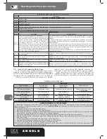
•• Visualization of inputs status
Press on the “OK” key to check if all inputs have been connected correctly
FC
C
2
SI
C
1
FC
A
1
FO
TO
C
FC
A
2
FC
C
1
SI
C
2
P
ED
O
N
ST
A
R
T
ST
O
P
By pressing the “ OK “ key when the control board awaits further
instructions (“- - - -”) the display shows some horizontal segments:
each one of them is associated to one of the control board inputs
(see the picture above). When the segment is lighted it means
that the contact associated to it is closed, on the contrary, when
it is switched off the contact is open. Now you must set the two
leaves in their respective full opening position. In order to do this:
•• Setup and memorization of motor stroke
WARNING
On ANGOLO 24/1 (single gate operator equipped
with control board) set parameter P.029=001 (“one-motor
function”); on ANGOLO 24/2 (single gate operator equipped
with control board + additional gate operator) set parameter
P.029=000 default parameter (“two-motor function”)
WARNING
During motors stroke memorisation, the control
board detects automatically the presence and type of photo-
cells, safety devices and limit switches which are installed. It is
therefore essential that during this phase the latter be properly
connected and working.
1
By pressing on the key the leaf must open, by pressing on the key the leaf
must close. If this does not happen, you must swap the two motor cables.
•• Built-in radio receiver
Control board includes a 433,92MHz built-in radio receiver
accepting both transmitters with HCS coding (complete rolling
code or just fixed part), and HT12E dip-switch coding.
• The type of coding is selected by programming the working
parameter n° 8 “type of coding” (see Table 2 Parameters)
• The receiver memory capacity can contain up to 100 different
transmitters.
• When receiving a pulse from the transmitter, depending on
your channel selection and linking, the start or the pedestrian
inputs are activated. In fact, by programming one of the
working parameters it is possible to choose, according to one’s
needs, which key of the memorized transmitters will activate
the start input and which one will activate the pedestrian input
(see “4. Channel selection and linking on the transmitter”).
•While you memorize each transmitter the display shows a
progressive number by which you will be able to trace and, if
necessary, delete each transmitter individually
Instruct.
Function
Display
The control board is ready to receive instructions
Deletion of all transmitters
Scroll down the parameters until you visualize P004
Confirm! The control board awaits a
further confirmation
Confirm by pressing on the OK key for a few se-
conds! The procedure starts
Done! The transmitters memory has been deleted
Scroll down the parameters until you visualize “----
”. The control board awaits a further confirmation
Memorization of transmitters
1
Scroll down the parameters until you visualize P005
Confirm! The receiver enters in memo-
rization mode
The flashing light flickers!
Press on any key of the transmitter.
Memorization done! The flashing light goes out
for 2 seconds. The display visualizes the number
of the transmitter just memorized (es. “r001”)
The receiver reverts automatically to me-
morization mode
The flashing light flickers!
Memorize all necessary transmitters
Wait 10 seconds before quitting the memori-
zation mode .The receiver will now receive all
the memorized transmitters
How to activate the memorization mode without
Operating on the control board
1
Press simultaneously on key CH1 and
CH2, or on the hidden key of a transmitter
already memorized
How to search and delete a transmitter
Scroll down the parameters until you visualize P006
Confirm! You can now select the transmit-
ter
Scroll down the transmitter numbers until you
reach the transmitter to be deleted (eg. “r003”)
Confirm the deletion by pressing the OK
key for a few seconds
OK! The transmitter is deleted
You can now select the parameter
Scroll down the parameters until you visualize “----
”. The control board awaits further instructions
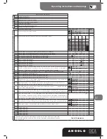
Instruct.
Function
Display
The control board is ready to receive instructions
Leaf 1 positioning
Scroll down the parameters until you visualize pro-
cedure P001
Confirm! The control board is ready for the positio-
ning of leaf 1
Position leaf 1 in its standstill posi-
tion while opening
1
Confirm! The control board has memorized the leaf
position
Leaf 2 positioning
Scroll down the parameters until you visualize pro-
cedure P002
Confirm! The control board is ready for the positio-
ning of leaf 2
Position leaf 2 in its standstill position
while opening
1
Confirm! The control board has memorized the leaf
position
Motors stroke memorization
Scroll down the parameters until you visualize pro-
cedure P003
Confirm! The control board awaits a
further confirmation
Confirm by pressing on the OK key for a few secon-
ds! The procedure starts
Now motor 2 starts to close in the slow down
phase until it reaches the stroke end while
closing (or the limit switch, if used), shortly
after that, motor 1 also starts to close in the
slow down phase until it reaches the stroke
end while closing (or the limit switch, if used).
On the display you will read “----”. Motor stroke
memorization done!


