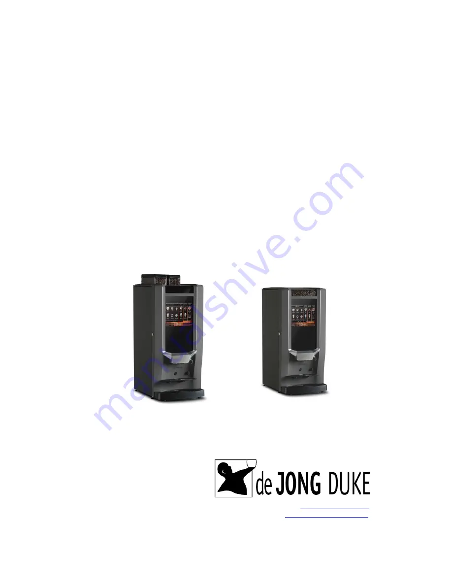
de Jong Duke COEX 9CND SERIES Technical Manual Download Page 1


Zia 6000 and 8000 

series 


Technical manual 

Model: Zia 6000 and Zia 8000 

Machine type: 9CND… 


Revision 1.0, English 

Reference: 5DTCNP20 


The manufacturer of the machine is: 


De Jong Duke 
Postbus 190 
3360 AD SLIEDRECHT 
The Netherlands 
Tel31 (0) 184 496767                                            

www.dejongduke.nl


Fax:         +31 (0) 184 416059 


[email protected]


Summary of Contents for COEX 9CND SERIES

Page 1: ...00 and Zia 8000 Machine type 9CND Revision 1 0 English Reference 5DTCNP20 The manufacturer of the machine is De Jong Duke Postbus 190 3360 AD SLIEDRECHT The Netherlands Telephone 31 0 184 496767 www d...

Page 2: ...r any damage resulting from incorrect or improper use of the machine or resulting from modifications that have not been authorized by the manufacturer This manual gives instructions for the operation...

Page 3: ...CHINE AND CABINET 10 3 5 COLD WATER UNIT IN BASE CABINET 11 3 6 WASTE GUIDE 11 3 7 DRIP TRAY DRAIN 11 3 8 FRESH MILK SYSTEM 11 3 9 PAYMENT SYSTEMS 12 3 10 MECHANICAL CONSUMPTION COUNTER 12 3 11 PUMP S...

Page 4: ...EPLACE SEALS IN LOWER PISTON 41 5 22 MIXER 42 5 23 GRINDER 46 5 24 GRINDER IN DOOR 47 5 25 REMOVING BEAN CANISTER AND GRINDER 47 5 26 GRINDING ADJUSTMENT 48 5 27 DEFAULT GRINDER SETTING 49 5 28 INGRED...

Page 5: ...R FILTER SETTINGS 78 7 18 RINSE 78 7 19 WEAKLY CLEANING CYCLE BREWER 78 7 20 SHOW PRODUCT COUNTERS 78 7 21 SOFTWARE INFORMATION 78 7 22 SHOW EVA DTS 79 7 23 CHANGE THE SERIAL NUMBER 81 7 24 FAN TURN O...

Page 6: ...e overseen by trained personnel 1 2 Safety risks The most important safety risks during maintenance of this machine Moving parts inside the machine beware of trapped fingers if the service key is plac...

Page 7: ...lean parts of the machine 1 5 Extended down time If the machine will not be used for a longer period of time for example during the holidays it is recommended to switch off the water supply and the el...

Page 8: ...can be made Before pressing start first a cup must be placed under the correct dispense nozzle 2 3 Overview of the machine interior 1 Bean canisters 2 On off switch 3 Instant canisters 4 Door switch 5...

Page 9: ...9 2 4 Backside of the machine 1 Water connection 2 Holes for water filter in base cabinet optional 3 Fan 4 Power cord 4 1 2 3...

Page 10: ...unted on the front of the base cabinet instead of an ingredient tray Part number 9BEB008 for cups 70mm diameter Part number 9BEB010 for cups 80mm diameter 3 3 Cup dispenser on right hand side Part num...

Page 11: ...Set to not available in the service menu see chapter 7 16 error settings In this case the wires on the waste bucket sensor needs to be electrical disconnected 3 7 Drip tray drain The water from the d...

Page 12: ...can be connected to the control board C Card reader in a side unit A card reader or key payment system communicating via the MDB protocol can be connected to the control board 3 10 Mechanical consumpt...

Page 13: ...75 mm 34 5 inch With increased bean canister 1025 mm 40 4 inch Weight empty 50 kg 110 lbs Electrical connection possibilities 120 VAC 60 Hz 1 3 kW 220 240 VAC 50 60 Hz 2 9 kW 220 240 VAC 50 60 Hz 1 5...

Page 14: ...h several options In the pictures below are the dimensions for a standard sized machine Door lock Front view Top view 795mm 31 3 inch 170mm 6 7 inch 295mm 11 6 inch 360mm 14 2 inch 170 mm 6 7 inch 160...

Page 15: ...duct information sheets for detailed information www dejongduke nl 4 6 Norms and standards The machine bears the CE marking and complies with the following directives regulations 2006 42 EC Directive...

Page 16: ...machines 5 1 Hot water system The water system is positioned at the back side of the machine and accessible from the back If water and power are connected and the door is closed the water system star...

Page 17: ...water supply Pressure reducer 0 9 bar C Pump 1 Pressure valve 2 bar 3 way outlet valve Drip tray Temperature and level sensor Boiler with heater Mixer Hot water 2 way outlet valve Expansion valve Flow...

Page 18: ...reduces the water pressure to a stable pressure independent from the inlet pressure from the mains water supply The required inlet pressure from the water supply is between 1 0 and 6 bar The pressure...

Page 19: ...rning the knob during the pump cycle of the espresso selection The manometer must show 0 8 0 9 bar during an espresso cycle 6 Lock the reducer by pushing the knob down towards it s own housing 7 Disco...

Page 20: ...measurement with the temperature probe also based on the quantity of incoming water The water flow meter is built in between the pressure reducer and the pumps It is a small turbine which produces ele...

Page 21: ...block pulse The pressure can be adjusted by the electrical signal pulse width to the pump A longer pulse gives a higher pressure because the plunger is lifted higher The maximum pulse width is 20 Thi...

Page 22: ...or two pumps The Fresh brew version without a bean hopper Zia 6000 has just 1 pump and is brewing coffee on a low 1 4 bar pressure The B2C espresso machine has 2 pumps parallel connected and can brew...

Page 23: ...teel The boilers are connected in serial water from boiler 1 flows into boiler 2 and from boiler 2 through outlet valves out of the hot water system The water inlet is in the bottom of the boiler the...

Page 24: ...white Heater neutral 5 Black Temperature safety 6 Brown white Temperature safety 7 Yellow grey Earth boiler housing Heater The boiler has a 1 4 KW 240VAC heater or a 1 1KW 110VAC The volume in the boi...

Page 25: ...Temperature The temperature is detected by a thermistor mounted in the stainless steel housing The control system is controlling the temperature in the boiler based on the resistance of the thermisto...

Page 26: ...the water The control system is detecting the water level because of this current 5 8 Position of valves in the hot water system The manifold with valves is connected straight on the boiler with a bol...

Page 27: ...l hole causing the air in the water to dissolve If this disc is not fitted tea made with hot water will have a foam layer and will not look appealing Part numbers 2 way valve 4EMV031 O ring 4ROR015 di...

Page 28: ...ositions the plunger in the original closing position on the valve thus cutting off the flow of the fluid The valve is controlled by 24VDC from the IO board Water connections Number Function Descripti...

Page 29: ...he valve is based on a spring together with the system pressure which is pressing the plunger on the valve seat The valve is controlled by 24VDC Water connections Number Function Description 1 Output...

Page 30: ...the maximum pressure in the system during standby is 2 bar 5 12 Safety pressure valve 12 bar The 12 bar pressure valve is a mechanical pressure valve in open line with the water system after the pump...

Page 31: ...nds very much on the condition of the brewer It is very important to keep the unit clean also for a good functionality Knob to remove filter Coffee funnel option Waste wiper Coffee outlet Espresso out...

Page 32: ...cessary for performing maintenance Carry out the following procedure for removal of the brewer Open the door of the machine Remove the outlet tube from the brewer Push the green handle upwards and pul...

Page 33: ...machine till you hear click and the green handle is turned downwards in its home position Make sure that the green handle is in the down position When the brewer isn t installed correctly the brewer...

Page 34: ...e piston into the coffee cake and flows through the filter screen out into the top and outlet of the brewer The pressure from the piston on the coffee cake is regulated by the adjustable current of th...

Page 35: ...35 Back to home After swiping the coffee cake away the brewer runs in the clock wise direction to the home position Start home position The brewer is ready for a new cycle...

Page 36: ...1 5 Nm Stall 1 8A 10 The motor is controlled in two directions clockwise and counter clockwise The position of the brewer is controlled by the micro switch and timers in the control system Electrical...

Page 37: ...wise To fit on brewer First place the complete upper piston in the right position then turn the know counter clockwise After replacing check if the upper piston is correct fitted If not correct replac...

Page 38: ...in the machine The duration time that the water is in contact with the coffee powder is a very important factor in the performance of the brewer and is about the same for coffee and espresso The optim...

Page 39: ...g enough to keep pressure switch in Coffee position The coffee channel is closed and the espresso is forced through the secondary restriction reducing the flow and increasing the pressure to 9 bar Thi...

Page 40: ...is not equipped with o ring sealing rings which seems an important malfunction factor In the following figure the impact of a coffee grain between the o ring and the cylinder is shown The grain will s...

Page 41: ...ver 2 Unscrew the bolt in top of the brewer and loosen the two other bolts 2 turns 3 Remove waste wiper 4 Push left and right housing sideward an pull the cylinder with piston out of the brewer 5 Repl...

Page 42: ...rms a cr me layer This will grade up the taste and the appearance of the consumption Motor specification 24VDC 14 000 RPM In case of a blockage a safety is actuated on the IO board and the message mix...

Page 43: ...ing the mixing system 1 Remove outlet pipes from the ingredient canisters 2 Turn the bayonet catch counter clockwise approx 10 3 Remove the mixer house by pulling it towards you 5 Pull the mixer blade...

Page 44: ...ase plate further counterclockwise and pull it towards you 7 Ready Assembling the mixing system 1 Install the base plate 2 Install the mixer blade Be sure that the arrow on the blade is at the flat si...

Page 45: ...45 3 Install the mixer house 4 Turn the bayonet catch clockwise 5 Install the outlet pipes on the ingredient canisters 6 Ready...

Page 46: ...wo metal blades to fine ground coffee These two blades in the grinder are mounted horizontally The upper blade in the grinder is a fixed blade and the lower blade is rotating driven by a motor of 24VD...

Page 47: ...ing a test drink with coffee from the grinder In this case unlock the grinder door with the green locking handle and rotate the grinder above the brewer 5 25 Removing bean canister and grinder Pull at...

Page 48: ...e will give a finer grinding by turning the screw counter clockwise and a coarse grained coffee by turning the knob clockwise After adjusting the grinder first take two consumptions to get rid of the...

Page 49: ...ards 2 3 Remove the upper grinder knife together with the black gear ring by rotating it counter clockwise 4 Be sure there are no beans left on the knifes and in the grinder housing Clean the knifes 5...

Page 50: ...adjusting worm wheel see chapter 5 26 grinding adjustment 5 28 Ingredient canisters The canisters can have a metal auger or plastic auger The metal auger is used for instant coffee instant tea and lea...

Page 51: ...Equipment The electrical system consists of the following main components Power supply board IO board Control board Display board with touch screen Inside machine Inside door Power supply IO board Co...

Page 52: ...the power supply has been equipped with a fuse The heating elements are directly connected to the mains via the On off switch and the IO board see chapter 6 8 schematic 1 The 5EPR078 a 120Watt power...

Page 53: ...nd payment systems The operating system counters and settings are saved on the control board Connections J1 IRDA Board J2 Speaker J3 mechanical counter J4 USB J5 USB J6 Touch screen J7 backlight J10 E...

Page 54: ...rs boiler s brewer motor mixers and valves Part number 5EPR132 27 outputs and 2 heater outputs J1 J2 Switching wires heater 1 J3 J4 Switching wires heater 2 J5 24Vdc input J6 In and outputs J8 Outputs...

Page 55: ...24V DC supply Red J5 2 24V DC supply Red J5 3 Black J5 4 Black J8 1 24VDC common Orange J8 2 Valve brew mix 1 Purple white J8 3 Ingredient motor 3 Blue White J8 4 Ingredient motor 4 White J8 5 Brew mi...

Page 56: ...evel detection 1 common Yellow Grey J6 1 24 volt DC common Orange J6 2 Pump 1 common Gray Blue J6 3 Pump 2 common Black Pink J6 4 Flow meter supply Red White J6 5 Flow meter signal Black Blue J6 6 Flo...

Page 57: ...57 6 5 LVDS Display and touch screen Part numbers Display LVDS 4EPR022 Touch screen 6CSS053 Control board 5EPR140 PCT controller 4EPR023 PCT controller 4EPR023 6 6 Speaker Part number 4ELP001...

Page 58: ...can be connected in the machine One for the right outlet and one for the center outlet A cup must be placed on the correct position on the cup stand before the start button is green and the cycle can...

Page 59: ...59 6 8 Electrical schematics Electrical Diagram MoVeC ICEQ 9CND 230Vac Electrical Diagram MoVeC ICEQ Controller board Zia...

Page 60: ...60 Electrical Diagram MoVeC ICEQ 9CND IOB connector J6 Electrical Diagram MoVeC ICEQ 9CND IOB connector J8 J9 en J10...

Page 61: ...ons who require a part of the machine to work will be in grey and will not function as long as the service key is not placed The rinse cycle grey in example picture will only work if the service key i...

Page 62: ...outlet nozzles before starting the rinse cycle Pressing the rinse button will start a rinse cycle for mixers and brewer directly Weekly cleaning cycle The weekly cleaning cycle needs to be done weekly...

Page 63: ...63 Software information This screen shows all types of software and hardware information about the machine...

Page 64: ...he login button left under The available service menu items Recipe settings Boiler temperature Cup sensor Select language Payment settings Software configurations Load permissions Clock time settings...

Page 65: ...10 Every step means 5 more or less product With this setting max 10 more or 10 less product from the average dosage is possible For milk creamer and sugar 3 strength steps are available If the strengt...

Page 66: ...ssure to see the water amount for this part of the recipe Water amount in main recipe the basis amount of water The water amount in the pressure boilers is adjusted in pulses generated from the flow m...

Page 67: ...ds after a fixed not visible delay Normally this delay is 0 5 seconds Water amount 100 The amount of water dosed through the topping mixer 100 100 pulses Delay for UI release Delay time at the end of...

Page 68: ...he desired boiler temperature The default settings Boiler 1 90 90 C 194 F Boiler 2 92 92 C 197 F Show boiler temperature will show the actual temperature of the boilers in degrees Celsius or degrees F...

Page 69: ...alue must be set low The default value is 100 This is the optimal value and gives the best detection for the most cup types If there are two cup sensors in the machine both are individual adjustable S...

Page 70: ...er pressing the return button on change giver or card reader Singe vend means you always receive your change or card direct after dispensing the consumption Overpay allowed Overpay allowed means that...

Page 71: ...u Select active configuration The back up file name exists of the original name added with an extension year month day and time Example Original file name 8124a00 mvq Backup file name 8124a00_14011214...

Page 72: ...the correct software is installed on the coffee machine MoVec ICEQ Version 3 40 or higher Flash file Version 1 7 or higher DJD software ID Version 4 0 or higher Collect coffee machine information vis...

Page 73: ...hine blocked Switch to free vend Use other pricelist Machine off Energy safe With the energy safe settings the machine can be switched to an energy safe mode during a period of time During this action...

Page 74: ...te month or year can be set as well if not used set to 0 Set all the values to 0 to switch off an action in the machine The value set in day month and year must be 0 if the action is daily required In...

Page 75: ...rect pixel size for the best result Please note that the machine does not auto scale the images Possibilities Load user logo A user logo or several user logo s can be loaded via an USB stick or via co...

Page 76: ...ages The delay between the consecutive images can be set in seconds Delete distributing images Delete a distributing image 7 14 Test outputs All outputs can be tested via the test output function Pres...

Page 77: ...Indicates the time before the message Rinse brewer with tablet is shown on the screen The time is indicated in seconds Clean brewer error Indicates the time before the message Rinse brewer with tablet...

Page 78: ...g and error show up after the set number of drink cycles is reached Reset water filter Selecting this button will reset the counter for the number of drink cycles to 0 The service key needs to be inst...

Page 79: ...ree Vend Summary VA301 Free Vend Value Of Sales Since Initialisation VA302 Number Of Free Vends Since Initialisation VA303 Free Vend Value Of Sales Since Last Reset VA304 Number Of Free Vends Since La...

Page 80: ...Cups 999 PA400 Free Vends By Product PA401 Number Of Free Vends Since Initialization PA402 Value Of Free Vends Since Initialization PA403 Number Of Free Vends Since Last Reset PA404 Value of free vend...

Page 81: ...he serial number is used if you use the EVA DTS function to readout data from the machine and for connect me functions 7 24 Fan turn off delay The fan will run the set time after the last consumption...

Page 82: ...cket Remove the back cover plate from the machine Remove the stop from the metal elbow or T coupling right after the pump s see picture Connect a 6 mm hose to the elbow Be sure the outlet of this hose...

Page 83: ...de the door 3 Wait for about half a minute the machine must see the stick first 4 Access the service mode on the machine and select the service menu 7 9 Software configurations 5 Select the option Loa...

Page 84: ...in the root directory 2 Insert the USB stick in the USB port of a working machine inside the door 3 The machine will recognize the files and upload these automatically The procedure takes max 60 secon...

Page 85: ...0 or higher 6 Within the software information screen locate the line CM X300 7 Write down the entire CM X300 serial number The number is 16 characters long and case sensitive Note If the CM X300 seria...

Page 86: ...e root directory of the USB stick for ease of uploading 3 Open the front door of the coffee machine 4 Place the prepared USB memory stick in the USB port at the inside of the front door Wait for half...

Page 87: ...12 Select the device 0 button device0 USB Memory stick inside door 13 Select the file xxx_key_xx mpf button May need to browse based on saved location of key file 14 The file is loaded 15 The beep in...

Page 88: ...ere to quit service button to exit the service menu 18 The coffee machine starts up again 19 When the normal operation screen is displayed the coffee machine is ready for normal use 20 Log in to the s...

Page 89: ...rrect Check the cable between the boards on damage A bad connection on control or IO board can generate this message Door open Close the door or install the service key in the door to run the machine...

Page 90: ...ket in the machine Mixer 1 2 blocked A too high current is detected on the output of the mixer motor Clean the mixing bowl check the motor Check recipes no dry powder should drop in the mixing bowl No...

Page 91: ...erature of 10 degrees more as the adjusted temperature is detected Check if heater is broken and keeps heating Check temperature setting Check temperature probe Check wiring loose bad contact Check th...

Page 92: ...92 Notes...

Page 93: ...93 Notes...

Reviews: