background image

De Gier B.V., Westlandseweg 9, 2291 PG  WATERINGEN, THE NETHERLANDS,

+31 (0)174 292089, [email protected], www.degierdrivesystems.com

Versie 1 – 2020 / 03 / 01

19

5.5 Commissioning

Caution!

Do not start the drive in the automatic mode, but use the manual operation setting on the climate computer.

After completion of the installation-, connection- and adjustment work on the motor gearbox, test-runs must be 

performed on the installation. When doing the test-runs, pay attention to the following points:

1.  Ensure that the work area of the motor gearbox plus coupled components is free of people and objects.

2.  Check whether the correct venting screw has been removed (see paragraph 4.1).

3.  Check the functioning of the installation in manual mode. The movement direction must match the indication on 

the control panel.

4.  Check the setting of the limit switches, and adjust them if required. (see paragraph 4.5)

Tip

Install an operating hours counter.

6. Use

6.1 Noise level

The noise level (sound pressure level) at one meter distance is below 60 dB(A).

6.2 Warming

•  The motor gearbox is not suitable for continuous operation.

•  The motor gearboxes are suitable for S3-30% operation.

•  The maximum allowed continuous running duration is 10 minutes.

•  The motor gearbox may not be started more than 3 times per minute.

Warning! Risk of burns! The exterior of the drive can reach a temperature exceeding 60 °C.

We recommend the fitting of a protective cover if the unit is within easy reach.

7. Inspection and maintenance

Inspection and maintenance work may only be performed by qualified staff (see paragraph 1.3).

7.1 Maintenance intervals

Mortal danger! Mortal danger due to electrical or mechanical forces!

Before starting to work on the motor gearbox and associated parts, always disconnect the power supply by 

means of the main or isolation switch and secure it against re-activation by using a padlock..

Every 6 months

Check on increased noise production

Every 12 months

•  Check mounting bolts and tighten if necessary

•  Check couplings for wear and corrosion

•  Check the limit switch system for corrosion

•  Check the set screws of the limit switch system and tighten if necessary

•  Check the electrical connection of the electric motor and the limit switch system

•  Check the play on the output shaft

5. Commissioning, use and maintenance

Summary of Contents for GXP10

Page 1: ...Installation instruction GXP P INS GXP 01 NL VERSIE 1 2020 03 01 Let s Gear Up ...

Page 2: ...request This partly completed machinery is in accordance with the provisions of the following European Directives European Machine Directive 2006 42 EG European EMC Directive 2004 108 EG The following harmonised standards or parts of these standards were applied NEN EN ISO 12100 1 2 04 2004 Safety of machinery Basic terms general design principles NEN EN ISO 14121 1 12 2007 Safety of machinery Ris...

Page 3: ...4 Technical specifications 5 1 Explanation of symbols and safety instructions 6 2 Productname and user instructions 8 3 Instructions for use 9 4 Mounting instructions 10 5 Electrical connection and commissioning 17 6 Use 19 7 Maintenance and disassembly 19 8 Dismounting 20 9 Troubleshooting 21 10 Replacing and removing parts 22 11 Disposal 22 12 Warranty 22 Glossary 23 13 Wiring diagram 400V 1 25 ...

Page 4: ...De Gier B V Westlandseweg 9 2291 PG WATERINGEN THE NETHERLANDS 31 0 174 292089 sales degierdrivesystems com www degierdrivesystems com Versie 1 2020 03 01 4 Dimensions ...

Page 5: ...2 230 1 1 8 12 23 P GXP10 230 40 KBS50 T 100 4 0 0 22 230 1 1 8 12 23 P GXP10 230 40 KBS50 02 T 100 4 0 0 22 230 1 1 8 12 20 P GXP10 400 40 KBS T 100 4 0 0 18 230 400 3 1 2 0 7 4 8 0 22 277 480 3 1 2 0 7 11 20 P GXP10 400 40 KBS32 T 100 4 0 0 18 230 400 3 1 2 0 7 4 8 0 22 277 480 3 1 2 0 7 12 23 P GXP10 400 40 KBS50 T 100 4 0 0 18 230 400 3 1 2 0 7 4 8 0 22 277 480 3 1 2 0 7 12 34 P GXP10 400 40 K...

Page 6: ... I Current A Tip Danger Remark Electrical hazard Instruction Explanatory note Tip Please note Caution Warning Mortal danger Provides the user with suggestions and recommendations to carry out certain tasks easier or more practical Remarks with supplementary information for the user A remark points out possible problems Material damage may occur when the procedures are not being followed diligently...

Page 7: ...ch or stationary heating Switching off the control using stop or 0 will not suffice Due to hierarchically higher functions such as wind or rain signals the motor gearbox could also start running in stop or null position Connected or driven parts could have a shorter technical lifespan than the motor gearbox itself In case of a three phase power supply swapping two out of the three phases will resu...

Page 8: ...Address details De Gier B V 2 3 Description The composition of the article number on the identification sticker shown above you will find underneath with an ex planatory note on the possible designs CODE SERIE Torque x 10 Nm Voltage V Speed revolutions x 10 1 rpm version tropical isulation P GXP 10 400 40 KBS50 T Possible designs K Suitable for coupling sleeves KBS32 Including two coupling sleeves...

Page 9: ... is not permitted to make constructional changes to the motor gearbox Any such modifications render the manufac turer s warranty null and void and relieve the manufacturer of liability for any consequences Additionally the following restrictions apply to the use of the motor gearbox Do not use the motor gearbox power train with a torque exceeding the indicated maximum torque Do not use the motor g...

Page 10: ...he motor gearbox was filled with the correct amount and type of oil during production Every motor gearbox is fitted with two red venting screws After installing the motor gearbox the highest positioned of the two red venting screws has to be removed A few drops of oil may run out of the vent hole during commissioning Hold on to the removed red screw and keep it with this manual 4 2 Installation of...

Page 11: ...d coupling sleeve 4 Attach the guidance bracket to the motor gearbox using the 3 included M8 bolts Use a tightening torque of 10 Nm 5 Attach the coupling sleeves to the output shaft using the included M6 bolts and nuts Use a tightening torque of 10 Nm Please note The outgoing shaft and the roll up tubes must be aligned A flexible coupling is required in case of alignment errors that cannot be solv...

Page 12: ...tube in three different ways as shown in the Illustration below ARTICLE CODE DESCRIPTION 1 P GXP10 40 xxx KBS xx T Complete GXP10 rol brack coupl sleeves 1A P GXP10 40 xxx xx T GXP10 motorgearbox 1B P BL 10 GXP10 Guidance bracket 1C P KBSxxx xx D19 Coupling sleeve 2 P BL 04 GXP10 Mount clamp top 3 P BL 02 GXP10 Mount clamp bottom 4 P KRP 15 16 xx Cable chain 5 Tube Ø32 mm Guid tube GXP to the righ...

Page 13: ...figurations f multiple screens are driven on one façade the configurations shown below are possible In configuration B all screens can be driven independently In the configurations C and D the motor gearboxes are installed onto 1 guide tube as a result of which they can run into each other see detail X These configurations are therefor only permitted when the screens are controlled simultaneously ...

Page 14: ... rotation direction II The emergency switch S21 or S22 is a safety provision and will be actuated only if the working switch S11 or S12 does not stop the motor gearbox on time The long set screw H of each switch nut E is placed inside the switch spring If one of both switch nuts reaches its stop nut the switch nut will rotate with the shaft and the long set screw will actuate the working limit swi...

Page 15: ...ol See the image on the next page Caution When driving the electric motor by means of a hexagonal tool a maximum speed of 250 RPM should be observed to protect the hexagonal socket on the rear of the electric motor shaft 5 Hand tighten the associated knurled nut D against its stop nut B 6 Place the included hexagonal wrench X into the long set screw H and turn the adjustment ring C across the knur...

Page 16: ...g limit switch Hexagonal wrench and spare set screws Adjustment of the limit switch Parts A Switch axle 1x B Stop nut 2x C Adjustment ring 2x D Knurled nut 2x E Switch nut 2x F Switch spring 2x G Short set screw 2x H Long set screw 2x Available tools and spare parts X Hexagonal wrench 2 mm Y Spare set screw M4x20 Z Spare set screw M4x6 Driving motor gearbox using hexagonal tool ...

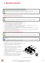
Page 17: ...to the limit switch and the control box Swap the live lead between V1 and W1 if necessary see image 7 Fit the protective cover and gasket of the terminal strip back onto the electric motor and tighten the cable gland 8 Ensure that the cables are clear of any moving parts 5 2 Mains connection for AC motors with 3 phases Caution Mains voltage may differ 10 at most from the voltage mentioned on the e...

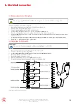
Page 18: ... a hexagonal tool 6 Check the rotation direction of the output shaft relative to the limit switch and the control box Swap the leads on A1 and A2 if necessary 7 Fit the protective cover and gasket of the terminal strip back onto the electric motor and tighten the cable gland 8 Ensure that the cables are clear of any moving parts 5 4 Connecting the limit switch Please note Take account of the maxim...

Page 19: ...The motor gearbox is not suitable for continuous operation The motor gearboxes are suitable for S3 30 operation The maximum allowed continuous running duration is 10 minutes The motor gearbox may not be started more than 3 times per minute Warning Risk of burns The exterior of the drive can reach a temperature exceeding 60 C We recommend the fitting of a protective cover if the unit is within easy...

Page 20: ...ismounting Dismounting may only be performed by qualified staff see paragraph 1 3 Mortal danger Mortal danger due to electrical or mechanical forces Before starting to work on the motor gearbox and associated parts always disconnect the power supply by means of the main or isolation switch and secure it against re activation by using a padlock Mortal danger Mortal danger as a result of falling obj...

Page 21: ... metal switch of the motor gearbox has tripped the motor gearbox must be left to cool down for approximately 20 minutes After this time the motor gearbox can be used again If this protection trips repeatedly contact your installer to resolve this problem 9 3 Malfunction end position passed Check whether all the set screws in the limit switch system are tight and check the setting of the limit swit...

Page 22: ...ately using a suitable emulsifier or absorbent material Dispose of the gears shafts and rolling bearings of the motor gearbox as steel scrap This also applies to the stain less steel cover plates unless there are provisions for separate collection The worm wheels are partly made of heavy non ferro metal alloys The lightweight metal gearbox housing is made of aluminium Dispose of these accordingly ...

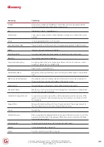
Page 23: ...switch operated by a pull cord along the entire length of the installa tion Elektrische aansluitwaarden The voltage current and power values that the electric motor was designed for These can be found on the rating plate of the electric motor Gevarenzone The area below or in the direct vicinity of the driven moving parts Hangende lasten Machinery or machine parts which are hanging from steel cable...

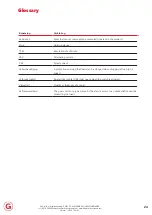
Page 24: ...t in the product Strop Hoisting device TPM Revolutions Per Minute VAC Alternating current VDC Direct current Valrembeveiliging A protection ensuring that loads can be stopped when dropping at too high a speed Verbreek contact An electrical contact NC that opens when the switch is actuated Viscositeit Fluidity or thickness of a liquid Zelfremmendheid The gear unit can only be driven by the electric...

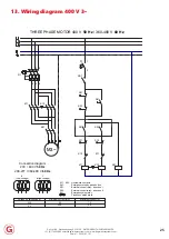
Page 25: ...K11 K12 S41 K41 Q1 1 2 3 4 5 6 M3 0 5 1 5 Maximum current A 200 24 50 230 Minimum current mA Voltage on limitswitch V S11 S22 Limitswitch contacts S41 Emergency stop by pass button S51 External control relay direction I S52 External control relay direction II K41 Emergency stop relay Fixed connection plate Connection diagram 230 400 V 50 Hz 208 277 360 480 V 60 Hz Y High voltage Δ Low voltage THRE...

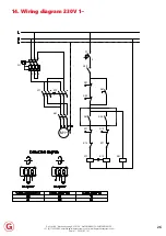
Page 26: ... WATERINGEN THE NETHERLANDS 31 0 174 292089 sales degierdrivesystems com www degierdrivesystems com Versie 1 2020 03 01 26 14 Wiring diagram 230V 1 S41 K12 K11 K11 K12 S12 S11 S52 S51 S22 S21 Q1 1 F1 1 2 K41 K11 M1 K41 6 5 4 3 2 1 Q1 K12 ...

Reviews: