


De Gier B.V., Westlandseweg 9, 2291 PG WATERINGEN, THE NETHERLANDS,
+31 (0)174 292089, [email protected], www.degierdrivesystems.com
Versie 1 – 2020 / 03 / 01
14
4.5 Limit switch setting
Use the following procedure and the figures on page 15 to set the integrated limit switches.
Functioning
• The switch axle (A) of the limit switch system is driven by the motor gearbox via a toothed belt transmission.
• On the switch axle (A) there are two switch nuts (E) consisting of a knurled nut (D) and an adjustment ring (C). The
adjustment ring can be secured to the knurled nut (D) by means of a short (G) and a long set screw (H).
• Depending on the rotation direction of the motor gearbox, the switch nuts (E) will move linearly across the switch
axle (A) into direction I or II. When the switch nut reaches the stop nut (B) at the end of the switch axle and is unable
to run any further, the switch nut (E) will start rotating with the switch axle (A).
• The limit switch is fitted with two switch springs (F) each of which actuates a working switch and an emergency
switch; either working switch S11 and emergency switch S21 for rotation direction I or working switch S12 and emer-
gency switch S22 in case of rotation direction II.
• The emergency switch (S21 or S22) is a safety provision and will be actuated only if the working switch (S11 or S12)
does not stop the motor gearbox on time.
• The long set screw (H) of each switch nut (E) is placed inside the switch spring. If one of both switch nuts reaches its
stop nut, the switch nut will rotate with the shaft and the long set screw will actuate the working limit switch corres-
ponding with the rotation direction. In the unlikely case that the activation of the working limit switch does not stop
the motor gearbox the emergency limit switch corresponding to that direction will be activated.
• rotating along of the gear nut ensures that maintenance- and emergency switches under the switch spring (F), cor-
responding with the rotation direction, are operated via the long set screw (H) the corresponding.
Installing the limit switch (as a standard pre-installed ex-factory)
1. Remove the stainless-steel protective plate of the motor gearbox;
2. Place the complete limit switch unit in the designated position;
3. Ensure that both of the long set screws (H) are located between the switch springs (F), so the switch spring loosens
the end and emergency switch when the switch nut starts rotating along with the shaft;
4. Secure the limit switch unit above the switch axle (A) by screwing both Phillips head screws hand-tight.
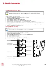
4. Setting the limit switches


