background image


3. 

Attach the enclosure rails to each side of chassis by positioning the rails 
over the keyhole tabs, and slide the rails into place. The rails are marked 
“R” (right) and “L” (left) viewing from the front of the enclosure. Do not 
exchange the enclosure rails. Secure each rail using seven #8-32 flat head 
screws (Figure 15b). 

4. 

With the new replacement SS8460 in place on the lift tool carefully position 
the lift tool in front of the rack (Figure 12) and raise the load plate up under 
the enclosure to be removed so that the load plate is now supporting the 
enclosure

.  Ensure the foot brake is applied and secure in position Figure 

13. 

5. 

Position the lift tool shelf and new replacement SS846 to the proper height 
to enable alignment of enclosure rails and rack rails and slide the rear 
alignment blocks on to the rack rails to align the enclosure properly with the 
rack rails.  

6. 

Carefully engage the enclosure rails into the rack rails and slide the 
enclosure in until the enclosure rail tabs “click” into place. The SS8460 
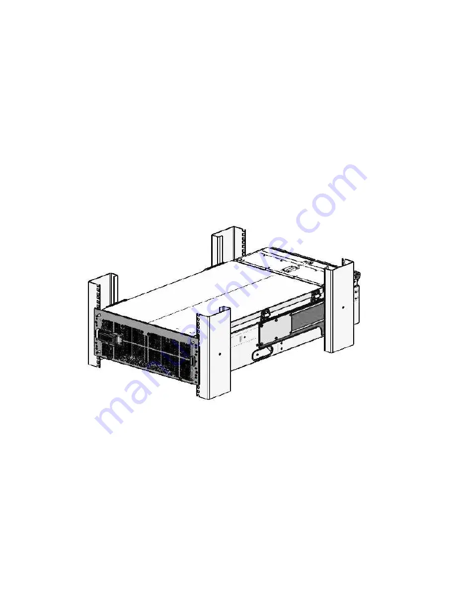
enclosure is now mounted in the rack (Figure 16).


Figure 16. Enclosure installed in Rack


7. 

Carefully reinstall all drives removed in previous steps by sliding the module 
into a disk slot until it contacts the baseboard and begins to engage the 
handle (Figure 11). Press down on the handle until it latches which will cam 
the module into place.


8. 

Reconnect the SAS cables, 

CMA cross bars.


9. 

Verify that the power switch on both PCMs is in the OFF position Figure 2. 

Summary of Contents for StorageScaler8460

Page 1: ...n overview of all the steps for installing a SS8460 system 1 Safety 2 Preparation 3 Power down of the system 4 Disconnect the SS8460 from the Storage Controllers or Expansion Enclosures 5 Removal of Suspect SS8460 Chassis from Current Configuration 6 Installation of New Replacement SS8460 ...

Page 2: ......

Page 3: ......

Page 4: ......

Page 5: ......

Page 6: ...e 2 0 0 Single SS8460 Power Down Procedure 1 Stop all I O to the SS8460 2 Perform a show subsystem summary command and note any faults not being corrected by the enclosure replacement total physical disks pool state virtual disk state and disk channel count 3 Note either the failed enclosure s ID or all the surviving enclosures ID s with a show enclosure command 4 Shutdown controllers with a shutd...

Page 7: ...isconnect the SS8460 from the storage controllers or expansion enclosures Each SS8460 ships with two fully redundant PCMs CAUTION If power cable replacement is required Use only the power cables supplied with the enclosure Do NOT use another type of cord or extension cords If you require additional power cables please contact your DDN sales representative 1 Verify that the power switch on both PCM...

Page 8: ...as needed 6 Verify that the cables and cable arm assemblies are such that cables won t get hung up and pulled on when the enclosure is removed 7 Slide the enclosure out from the rack by pushing in the two release tabs on front of the enclosure Figure 6 Keep pulling until the enclosure locks and you hear a clicking The unit should now be out enough to open top covers Figure 6 Release Tab on Enclosu...

Page 9: ...tside Use Velcro to tie back in a safe place Note that for SFA subsystem installation not all host ports are used on the I O modules Refer to the cable maps given in the SFA OS User Guide to determine which host ports are used Figure 6 Cable Positions in CMA Figure 7 CMA Cross Bar Removal 9 Remove the CMA cross bar on the rear panel of the enclosure by removing two 10 32 screws as shown in Figure ...

Page 10: ...d inside the cover of the enclosure Refer to Appendix B for information on zoning configuration 1 Prepare an area such as a table located in close proximity to the SS8460 you are working on for placement and temporary storage of the removed disc modules NOTE It is highly recommended that each disc module and blank be labeled with its current installed location within the SS8460 prior to removal 2 ...

Page 11: ...event it from being dropped Figure 9 Cover Release Handles When removing the disk modules Create a more balanced load by evenly distributing the disk modules among the enclosures Always remove the rows from back to front Note that disks with similar rotational speeds are placed in the same row if a mixture of disk technologies are populated into one enclosure for optimal performance the best loadi...

Page 12: ...k Module 5 Carefully slide the module from the disk slot Figure 11 Figure 11 Removing Disk Modules 6 Repeat Steps 4 and 5 above to remove all the remaining disks and blank modules 5 0 Removal of Suspect SS8460 Chassis from Current Configuration 1 Carefully position the lift tool in front of the rack Figure 12 and raise the load plate up under the enclosure to be removed so that the load plate is n...

Page 13: ...Figure 12 Proper Lift tool Place in Front of the Rack ...

Page 14: ...ails from the rack rails and slide the rack rail back into the rack Figure 14a and 14b The SS8460 Enclosure is now dismounted from the rack Adjust Load plate up and down as necessary for ease of enclosure removal Figure 14a Detach Enclosure Rail from Rack Rail Right Side Figure 14b ...

Page 15: ...3 Re Use the packaging material from the new replacement unit to repack the suspect unit for proper return ...

Page 16: ...osure Two power cables Rack mounting hardware Cable management hardware SS8460 user documentation CD Disk modules Blank modules if ordered Before you unpack your SS8460 inspect the shipping containers for damage If you detect damage report it to your carrier Retain all boxes and packing materials in case you need to store or ship the system in the future Perform the following steps 1 Open the top ...

Page 17: ...llation c Ensure ahead of time that you have chosen a suitable location for the enclosure or rack assembly 7 Ensure that the area around the enclosure or rack assembly has sufficient cooling and space around the unit to access cabling 8 When installing disk modules allow them to acclimate to room temperature prior to installation Disks should be stored at room temperature for at least two hours pr...

Page 18: ... the rack rail until it is fully extended Then press the locking tab down to release the enclosure rail Figure 15a and B Press the locking tab on the middle rail and push it back into the rack rail Repeat for the other rack rail Figure 15a Detach Enclosure Rail from The Right and Left Sides Right Side shown or remove from suspect unit SS8460 Rail Right Side Figure 15 b ...

Page 19: ... the lift tool shelf and new replacement SS846 to the proper height to enable alignment of enclosure rails and rack rails and slide the rear alignment blocks on to the rack rails to align the enclosure properly with the rack rails 6 Carefully engage the enclosure rails into the rack rails and slide the enclosure in until the enclosure rail tabs click into place The SS8460 enclosure is now mounted ...

Page 20: ...hit return to stop the output iv Show enclosure X all verify zoning change took affect 5 Perform a show subsystem summary command and note any faults not being corrected by the enclosure replacement total physical disks pool state virtual disk state and disk channel count 6 0 5 Multiple SS8460 Power up Procedure CAUTION The power up order is critical for each of the expansion enclosures to properl...

Page 21: ...tal physical disks pool state virtual disk state and disk channel count 6 0 6 Repack Suspect SS8460 and IBM Lift tools 1 Repack the suspect SS8460 in the box that the new replacement came in for safe FRU return shipment by performing the unpack steps in reverse order 2 Repack IBM Lift tools for return to Tools Depot by following the instructions provided with the tool For complete Support Instruct...

Page 22: ...Appendix A Product Specifications ...

Page 23: ...n all installed disks are presented to all the host ports on both I O modules Figure 16 Figure 16 Zoning Configuration 0 Disk Presentation Zoning Configuration 1 When zoning configuration 1 is active the devices are divided into two groups of 42 disks as shown in Figure 17 Figure 17 Zoning Configuration 1 Drive Groups ...

Page 24: ...Figure 18 Zoning Configuration 1 Disk Presentation End of Document ...

Reviews: