


24
6.9 Show room mode
Show Room Mode is used mainly by salespersons and distributors. When the unit is in Show Room Mode, it will operate as if func-
tioning normally; however, the internal components will not run.
Enabling Show Room Mode:
To enable Show Room Mode, press and hold the “ON/OFF” button while performing a “Power On Reset” (POR), i.e. - disconnect
and reconnect the power supply to the unit. When Show Room Mode is enabled, the compressor, condenser fan, internal fan(s),
heater, reverse gas solenoid, and alarms are disabled. The display will show the last set point entered.
Disabling Show Room Mode:
To exit Show Room Mode, initiate a “Power On Reset” (POR) only.
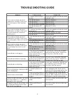
6.10 error code detection
The microprocessor in the control continually monitors critical refrigeration system components for proper operation. If compo-
nent parameters exceed normal operating specifications, an audible alarm will sound six times every minute and the display will
automatically flash the respective error code. If multiple errors are noted with the unit, the error codes will be displayed sequen-
tially. See Table D: Error Code Detection Reference for respective error codes descriptions and the potential causes of failure.
Table D: Error Code Detection Reference
Error Code
Error Code Reference
Potential Causes of Failure
E1
Compressor fault (high/low amps)
1. Compressor wires disconnected.
2. Faulty compressor.
3. Faulty control.
4. Faulty compressor overload.
5. Faulty compressor PTC starter.
E2
Condenser fan motor fault (high/low amps)
1. Condenser fan motor wires disconnected.
2. Faulty condenser fan motor.
3. Faulty control.
E3
Evaporator thermistor “sensor B” fault (out-of-range)
1. Disconnected wire causing open.
2. Shorted thermistor wires.
3. Faulty thermistor.
E4
Display thermistor “sensor A” fault (out-of-range)
Resetting Error Codes:
Error Codes can only be reset by disconnecting and reconnecting the power supply to the unit.
6.11 Service diagnoSticS mode
Service Diagnostics Mode allows you to identify the firmware and software versions, test status of “model specific” system compo-
nents and sensors, and change state of components where applicable (i.e. - compressor on/off, etc...).
Enabling Service Mode:
To enable Service Mode, press and hold the “WARMER” button while pressing the “COLDER” button four (4) times within five (5)
seconds.
You cannot enable Service Mode while in Set Mode.
•
All system functions will remain in their current state while in Service Mode.
•
Alarms are disabled during Service Mode and reset after exiting Service Mode.
•
Service Mode will automatically disable after five (5) minutes of no keypad entry.
•
uSEr INTErFACE PANEL ANd CONTrOL SYSTEM
rEFrIGErATION MONITOr
Summary of Contents for RF24-D
Page 1: ...1 DCS REFRIGERATED DRAWERS Service manual Model RF24D ...
Page 2: ......
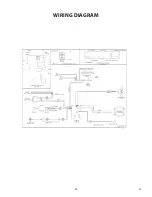
Page 30: ...28 23 WIRING DIAGRAM ...
Page 36: ...34 NOTES ...
Page 37: ...35 NOTES ...
Page 38: ...36 NOTES ...
Page 39: ......