


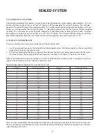


8
INSTALLATION
HOW TO INSTALL YOur OuTdOOr rEFrIGErATEd drAWEr
2.9 Select location
The proper location will ensure peak performance of your appliance. Choose a location where the unit will be out of direct
sunlight, away from heat sources and moisture. Units with fan cooled condensers can be built in. Unit should be operated
in a properly ventilated area with ambient temperatures above 40 degrees and below 100 degrees Fahrenheit.
Installation should be such that the cabinet can be moved for servicing if necessary.
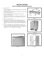
2.10 caBinet clearance:
Ventilation is required from the bottom front section of the unit. Keep this area open and clear of any obstructions.
•
The adjacent cabinets and counter top can be built around the unit as long as no top trim or counter top is installed
•
lower than the top of the upper drawer. See Fig. 2.5.
2.11 Side trim inStallation
Prior to installation, align trim with the refrigerated drawer height and mark the screw hole locations. Attach side trim to
the inner side of the cabinet so that the trim faces outward (away from the appliance’s door) and fasten with appropriate
screws suitable for the type of cabinet material (Fig. 2.6).
2.12 inStalling drawerS
Place the unit in front of the counter opening. Make sure that the floor is protected when sliding the drawer unit into
•
place.
Determine the minimum height of the counter top opening (Fig. 2.5).
•
Lower the front and rear leveling legs (Fig. 2.5) so the top of the drawer cabinet is 1/8” lower in the back of the
•
cabinet and 1/2” lower in the front of the cabinet than the counter top opening.
Make the electrical connection by plugging the unit into the power outlet and locating the power cord so it will not be
•
damaged when the refrigerated drawer is installed.
Slide the refrigerated drawer into cabinet location and adjust the front legs until the unit is level and there is the same
•
amount of load on each leg.
24” Outdoor Refrigerated Drawers
15-1/8
15-1/8
3-1/2”
24-1/8
Dimensions
Island Preparation
Side Trim Installation
Mounting
screw not
provided
Figure 2.4
Figure 2.5
Figure 2.6
Summary of Contents for RF24-D
Page 1: ...1 DCS REFRIGERATED DRAWERS Service manual Model RF24D ...
Page 2: ......
Page 30: ...28 23 WIRING DIAGRAM ...
Page 36: ...34 NOTES ...
Page 37: ...35 NOTES ...
Page 38: ...36 NOTES ...
Page 39: ......


