Driverack
®
4800/4820 user Manual
6.17 - Limiter Insert
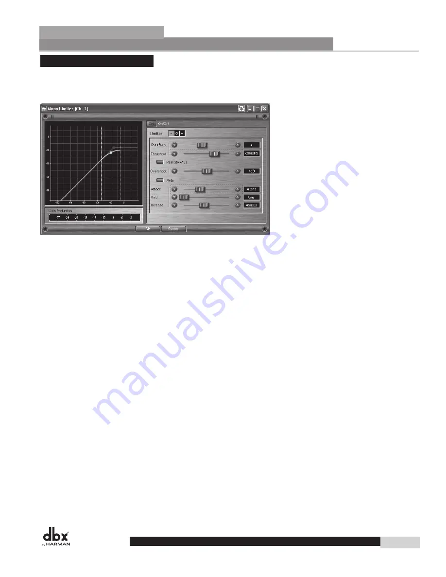
The DriveRack 4800/4820 units offer a Limiter in the Output Insert position. A Limiter operates on the
same principles as a compressor (see section 6.14) but it is designed and used more for system protection
rather than musical dynamics control.
Limiter on/off switch
This turns the Limiter module on and off.
overeasy fader
OverEasy is a characteristic of dbx Compressor/Limiters is essentially a “soft-knee” function that occurs
about the threshold. On analog devices, OverEasy can only be turned on or off, but in the digital domain
this parameter can have a range. This parameter can be adjusted between 0 and 10 where 0 corresponds to
no OverEasy, and 10 correspond to a very wide soft-knee region.
threshold fader
The Threshold is the signal level at which the unit begins to limit the signal. If the level is set to -10 dBFS,
then any signal larger than -10 dBFS is reduced in gain. The range of the Threshold fader is -60 to 0dBFS.
PeakStopPlus on/off switch
This switch engages PeakStopPlus
®
and changes the Limiter from an RMS (Root Mean Squared) or aver-
aging limiter to a peak limiter. The difference between these two types of limiters is in the signal that is
being fed to the detection circuit or algorithm. The detector of an RMS limiter is “looking” at an average
signal, while a peak limiter “looks” at the instantaneous signal. An averaging limiter will be less responsive
and will not actually limit every peak where a peak limiter will.
PeakStopPlus overshoot fader
In the DriveRack when PeakStopPlus is engaged the algorithm allows selection of how much a transient
signal will be allowed to pass the limiter threshold before it is stopped. This amount is the Overshoot.
Overshoot can be adjusted between 2 and 6dB.
auto on/off switch
Auto mode dynamically sets the Attack, Hold, and Release parameters in real time based on the incoming
signal. This switch turns the Auto mode on and off.
Detailed Parameters
Section 6
59
DriveRack
®
Summary of Contents for DriveRack 4800
Page 1: ...User Manual 4800 4820 CompleteEqualization LoudspeakerManagementSystem...
Page 6: ...DriveRack...
Page 7: ...features Customer Service Info WARRANTY INFO INTRODUCTION DriveRack Introduction...
Page 10: ...Introduction DriveRack 4800 4820 User Manual DriveRack iv...
Page 11: ...Rear panel front panel software installa tion Getting Started Section 1 DriveRack...
Page 18: ...Getting Started 8 Section 1 DriveRack DriveRack 4800 4820 User Manual...
Page 19: ...Presets attributes DriveRack Philosophy Section 2 DriveRack...
Page 21: ...navigation modes Front Panel Operation Section 3 DriveRack...
Page 29: ...moduleview deviceview venueview Software Operation Section 4 DriveRack...
Page 40: ...Software Operation 30 Section 4 DriveRack DriveRack 4800 4820 User Manual...
Page 41: ...31 front panel operation SOFTWARE OPERATION In Use Section 5 DriveRack...
Page 48: ...In Use 38 Section 5 DriveRack DriveRack 4800 4820 User Manual...
Page 49: ...Detailed Parameters Detailed Parameters Section 6 DriveRack...
Page 73: ...UTILITIES Section 7 Utilities DriveRack...
Page 77: ...DriveRack Appendix...
Page 80: ...Appendix DriveRack DriveRack 4800 4820 User Manual 70 A 2 Block Diagram...
Page 86: ...Appendix DriveRack DriveRack 4800 4820 User Manual 76 A 8 ZC 4 Wiring Diagram...
Page 95: ...Appendix DriveRack DriveRack 4800 4820 User Manual 85...


