


Section 1
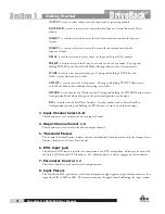
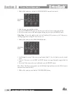
9. Status LeDs
This cluster of four LEDs indicate the following functions:
ClIP - indicates either A/D, D/A, or DSP clipping.
syNC - indicates DSP syncing to an internal clock, AES/EBU, CobraNet, or Wordclock input.
rs-232 - indicates PC connection via RS-232.
lINK/aCt - indicates connection to and/or activity on an Ethernet network.
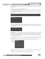
10. output adjustment/Mute Knobs 1-8
The Output Trim/Mute knobs provide Trim Gain adjustment of each output. Pressing the knob
mutes that output.
11. output Meters
The DriveRack 4800 provides eight independent eight segment output headroom meters that range from SIG
(-48dB) to 0dB.
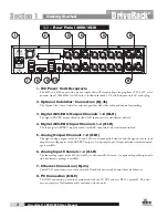
1.3 - front Panel (4820)
7
1
4
5
2
3
6
8
1. rta Input Jack
This balanced XLR input is used for the connection of an RTA microphone, which may be used with
the Auto EQ function in the Wizard. 48V phantom power is always engaged on this connector.
2. Serial Pc connection (DB-9)
This DB-9 connection is used to communicate to the System Architect control software and uses
RS-232 protocol. This connection requires a Null Modem cable and one is included with the unit.
3. alpha numeric Display
This display shows the ID# of the DriveRack 4820 unit. It can also show various error codes.
4. Input Meters
The DriveRack 4820 provides four independent eight segment input headroom meters that range from
SIG (-48dB) to 0dB. These meters monitor the signal directly following the input section.
5. Status LeDs
This cluster of four LEDs indicate the following functions:
Getting Started
5
Driverack
®
4800/4820 user Manual
Getting Started
DriveRack
®
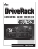
Summary of Contents for DriveRack 4800
Page 1: ...User Manual 4800 4820 CompleteEqualization LoudspeakerManagementSystem...
Page 6: ...DriveRack...
Page 7: ...features Customer Service Info WARRANTY INFO INTRODUCTION DriveRack Introduction...
Page 10: ...Introduction DriveRack 4800 4820 User Manual DriveRack iv...
Page 11: ...Rear panel front panel software installa tion Getting Started Section 1 DriveRack...
Page 18: ...Getting Started 8 Section 1 DriveRack DriveRack 4800 4820 User Manual...
Page 19: ...Presets attributes DriveRack Philosophy Section 2 DriveRack...
Page 21: ...navigation modes Front Panel Operation Section 3 DriveRack...
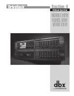
Page 29: ...moduleview deviceview venueview Software Operation Section 4 DriveRack...
Page 40: ...Software Operation 30 Section 4 DriveRack DriveRack 4800 4820 User Manual...
Page 41: ...31 front panel operation SOFTWARE OPERATION In Use Section 5 DriveRack...
Page 48: ...In Use 38 Section 5 DriveRack DriveRack 4800 4820 User Manual...
Page 49: ...Detailed Parameters Detailed Parameters Section 6 DriveRack...
Page 73: ...UTILITIES Section 7 Utilities DriveRack...
Page 77: ...DriveRack Appendix...
Page 80: ...Appendix DriveRack DriveRack 4800 4820 User Manual 70 A 2 Block Diagram...
Page 86: ...Appendix DriveRack DriveRack 4800 4820 User Manual 76 A 8 ZC 4 Wiring Diagram...
Page 95: ...Appendix DriveRack DriveRack 4800 4820 User Manual 85...


