background image

Editing Functions

®

6

Section 2

DriveRack

The 240 DriveRack™ has been carefully designed and engineered to ensure that all aspects of
operation are intuitive and logical.  Simply stated, the 240 DriveRack™ operating system was
designed with user’s best interest in mind.  Editing the 240 DriveRack™ can be done by utiliz-
ing  key functions and tools.  This section will provide you with detailed information on all of
the tools used to optimize the editing performance of your 240 DriveRack™ via the front panel.  

Navigational aspects of the 240 DriveRack™ are clear, concise and more important: flexible.
The DriveRack™ provides you with essentially three different modes of navigation when per-
forming program edits.  

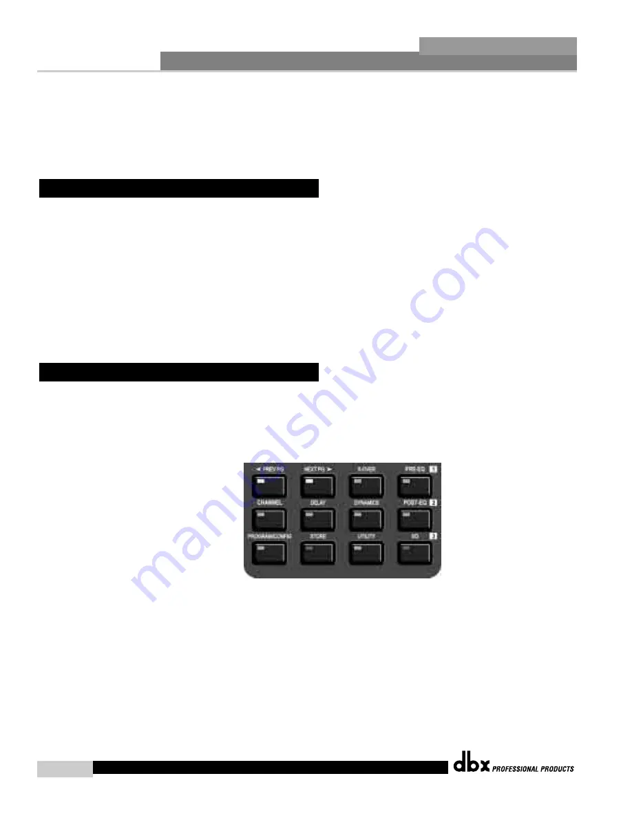
1

FX

buttons - This array of 12 FX buttons is your primary mode of

directly accessing any effect module.  

2

NEXTPG

PREVPG

page buttons - Successive

presses of the 

NEXTPG

or 

PREVPG

page buttons will move the user from one page to the

next in an effect block. 

3

Data Wheel  - 

The Data Wheel is used to move through the pro-

gram menu of the 240 DriveRack.  The Data wheel is also used to change the values of the
selected parameter by simply rotating the wheel.  Pressing the Data wheel will toggle between
the available parameters on any selected page of the currently selected effect module.

The following will provide you with detailed information for accurate navigation of the FX but-
ton section of the 240 DriveRack™. Each diagram indicates the functionality of each FX button
and its ability to guide the user through each operational menu.  

2.2 FX Button Array Overview

2.1 Basic Navigation Modes

Editing
Functions

DriveRack™ User Manual

Summary of Contents for DriveRack 240

Page 1: ...User Manual CompleteEqualization LoudspeakerManagementSystem 240 241...

Page 2: ...A POWER CORD WARNING THIS APPLIANCE MUST BE EARTHED The cores in the mains lead are coloured in accordance with the following code GREEN and YELLOW Earth BLUE Neutral BROWN Live As colours of the cor...

Page 3: ...ribyte Anv nd samma batteri typ eller en ekvivalent typ som rekommenderas av apparattil lverkaren Kassera anv nt batteri enligt fabrikantens instruk tion IMPORTANT SAFETY INSTRUCTIONS ELECTROMAGNETIC...

Page 4: ...Parameters 4 1 Input Routing 20 4 2 1 Pre Crossover EQ 31 Band Graphic 20 4 2 2 Pre Crossover EQ 9 Band Parametric 20 4 4 Delay Pre Crossover 21 4 5 Crossovers 22 4 6 Post Crossover Parametric EQ 26...

Page 5: ...INTRO CUSTOMER SERVICE INFO Defining the DriveRack WARRANTY INFO INTRODUCTION DriveRack...

Page 6: ...and the power amps The following are just some of the features of the 240 and 241 DriveRack units 240 DriveRack features 2 Inputs and 4 Outputs Fully functional user interface Balanced XLR and Euroblo...

Page 7: ...aken the time to fill out your warranty registration card and send it in please do so now Before you return a product to the factory for service we recommend you refer to the manu al Make sure you hav...

Page 8: ...m the factory where all parts and labor will be covered up to a period of two years A Return Authorization number must be obtained from dbx by tele phone The company shall not be liable for any conseq...

Page 9: ...low Note XLR and Euroblock connectors are wired in parallel Make output connections from any one of the four output XLR or Euroblock connec tors shown below to the input of the selected power amp If a...

Page 10: ...el is also used to perform editing functions to effects and utility menu features Button Array Operational editing is done using this 12 button array A com plete description of each button s functiona...

Page 11: ...Getting Started Section 1 DriveRack...

Page 12: ...s two electronically balanced XLR and Euroblock connectors Note Do not use both input types XLR and Euroblock simultaneously Ground Lift Switch The ground lift switch lifts the pin 1 chassis ground of...

Page 13: ...ted for the 22dBu set ting of the gain jumpers Output Mutes The four output mute buttons are used for independently muting each output of the 240 DriveRack Power Switch Turns the 240 DriveRack on and...

Page 14: ...onnectors as well as the chas sis ground connector of the euroblock input connector PC Connection This DB 9 type connection is used to send and receive information to and from the computer running the...

Page 15: ...EDITING FUNCTIONS Editing Functions Section 2 DriveRack...

Page 16: ...This array of 12 FX buttons is your primary mode of directly accessing any effect module 2 NEXTPG PREVPG page buttons Successive presses of the NEXTPG or PREVPG page buttons will move the user from on...

Page 17: ...sor Limiter effect menu Successive presses will move through the dynamics modules POST EQ Selects the Post EQ effect menu This is the EQ section after the crossover section Successive presses will mov...

Page 18: ...ted page 2 4 Navigating the Post crossover EQ Section The EQ button toggles through the EQs used in each channel of the selected program menu PEQ GEQ or To edit the parameters of the EQs used in a sel...

Page 19: ...ly use the following procedure From program mode press the X OVER button Once you have reached the Crossover module Navigate through the Pages of the selected Crossover module by pressing the Next Pag...

Page 20: ...gram mode either press the I O button Successive presses will move through each of the Input and Output editing modules Pressing the Data Wheel will select the effect parameter to be edited Successive...

Page 21: ...CONFIGURATION FUNCTIONS SOFTWARE Section 3 DriveRack...

Page 22: ...mbined make up the conventional program and that they are all unique to each individual program The Utility menu mode is accessed via the utility menu and is not part of a single program From the fact...

Page 23: ...resses will you move through each input and output which utilizes the Delay type module DYNAMICS Compressor Limiter successive presses will move you through each output compressor module POST EQ PEQ m...

Page 24: ...ke this If you wish to replace an existing program press the 1 Pre EQ button and the unit will ask you which program you wish to replace Rotate the DATA wheel to select the program to be replaced and...

Page 25: ...ld the PROGRAM CONFIG button until the dis play briefly reads CONFIGURATION At this point you will be entered into configuration mode at the Pre Crossover EQ section and the display will now appear as...

Page 26: ...eparate Once you are satisfied with your selections on this page press the NEXT PAGE button which will move you to the next page which will appears as follows Rotate the DATA wheel to select the appro...

Page 27: ...h range on one linked channel will cause gain reduction on all of the linked channels Once you have edited and moved through the three post crossover effect modules the next display will appear as fol...

Page 28: ...am or turning the power off Once changes have been made to the current Configuration changes can be saved by pressing the STORE button and the display will appear like this At this point enter the new...

Page 29: ...DETAILED PARAMETERS PARAMETERS Section 4 DriveRack...

Page 30: ...selected channel Master level Inf to 20dB This parameter is used to control the overall output level of the mixed input signals The 240 and 241 DriveRack Pre Crossover EQ sections may be configured as...

Page 31: ...elected band of the parametric EQ Q 2 8 0 20 to 16 0 Adjusts the Q of the selected band of the parametric EQ Level 2 8 12 to 12 dB Sets the overall level of the selected parametric EQ frequency Band 9...

Page 32: ...s respectively A crossover point is where the Lowpass and Highpass filter meet The user may control the Lowpass edge or Highpass edge The Crossover type allows selection of Butterworth Bessel or Linkw...

Page 33: ...ossover frequency High Frequency rolloff 1 20Hz to 20kHz Selects the desired Highpass crossover frequency Type 1 Butterworth BW Bessel BS and Linkwitz Riley L R Selects the desired crossover filter ty...

Page 34: ...pass crossover frequency Type 2 Butterworth BW Bessel BS and Linkwitz Riley L R Selects the desired crossover filter type Low Slope 2 6 24dB Octave BW Bessel 12 24dB Octave L R Sets the Lowpass slope...

Page 35: ...red crossover filter type Low Slope 2 6 24dB Octave BW Bessel 12 48dB Octave L R Sets the Lowpass slope of the crossover filter High Slope 2 6 24dB Octave BW Bessel 12 48dB Octave L R Sets the Highpas...

Page 36: ...igure shows the constant Q parametric filter Flatten Restore This parameter either flattens the PEQ or restores the PEQ to its original shape Type This parameter selects the PEQ type Types include 1 L...

Page 37: ...nits start to compress the signal If the level is set to 10 dBu than any signal larger than 10 dBu is compressed while any signal that has a level that is lower than 10dBu is left at the same signal l...

Page 38: ...ponents such as high frequency mid frequency and low frequency drivers within a speaker cab inet Delay On Off Turns the Speaker Alignment delay on and off Units MS milliseconds Feet or Meters Selects...

Page 39: ...UTILITIES SECTION Utilities Section 6 DriveRack...

Page 40: ...ss to the system The following information is provided to help you set all security parameters Prior to setting security passwords you will access the security menu by pressing the UTIL ITY button and...

Page 41: ...e between upper and lowercase letters number and symbols Use the PREV PG and NEXT PG button to move icon positions Once the desired title has been written press the STORE button and the display will n...

Page 42: ...this procedure at any time simply press PROGRAM CONFIG button Press the PROGRAM CONFIG button to return to normal operation After a user with medium or high clearance has completed any edit changes he...

Page 43: ...tton and the display will appear as follows The index number is the position of the selected program in the list To change the index number when it is selected simply rotate the DATA wheel To set the...

Page 44: ...selected proceed to rotate the DATA wheel until the desired mute setting All Saved or SyS Mute is selected All All outputs muted on powerup Saved Outputs mutes on pre vious power down and SYS Mute the...

Page 45: ...ion from within the 240 the procedure is as follows From Program mode press the UTILITY button and use the PREV PG and NEXT PG button to move to the page that appears as follows Note that the undersco...

Page 46: ...have selected the program that you wish to add latching functionality to press the DATA wheel until Latch is selected for editing You can move through the options available for latch set up ie OFF On...

Page 47: ...DriveWare GUI Section 6 DriveRack...

Page 48: ...he CD ROM onto your your PC or laptop Once the software is downloaded or CD is loaded simply double click on the file named DriveRack setup The application will proceed to ask you where you want the p...

Page 49: ...mode of operation to best suit your needs it is recommended that at this point you set your desired preferences in the preference folder which can be accessed in the file menu and will appear as follo...

Page 50: ...GUI Install 40 SECTION 6 DriveRack Note The Baud rate must be set to 38400 GUI Recommended Cable Specifications PC GUI Interface DB 9 female to female nul modem cable 10 feet DriveRack User Manual...

Page 51: ...APPLICATION GUIDE Section 7 DriveRack...

Page 52: ...ss audio applications Hardware Note Make sure that all outputs are muted on the DriveRack prior to adding power to any devices in the signal path pre and post DriveRack 1 Connect the outputs from the...

Page 53: ...LR w Delay as a template 2 Once the program has been chosen press the PROGRAM CONFIG button to load the pro gram 3 Please see sections 3 and 4 configuring and detailed parameter for more information o...

Page 54: ...r to the mixer and amplifiers Software 1 From Program mode select factory program 23 Mono LCR w Sub as a template 2 Once the program has been chosen press the PROGRAM CONFIG button to load the pro gra...

Page 55: ...1X4 with filters crossover configuration 2 Store four separate copies of this preset with names such as Zone 1 4 3 Adust the EQ Time alignment delay and limiter for each preset Zone 4 Now modify each...

Page 56: ...sure that all outputs are muted apply power to the mixer and amplifiers Software 1 From Program mode select factory program 27 Delay Speakers as a template 2 From program mode calculate and edit each...

Page 57: ...241 2 Connect the output of the 240 241 to the return of the mixer 3 Making sure that all outputs are muted apply power to the mixer and amplifiers Software 1 From Program mode select factory program...

Page 58: ...4 Make connections from switch closure output on the 240 241 to the wall mount control switches optional Software 1 Select a program that uses a 1X4 with filters crossover configuration 2 Store three...

Page 59: ...Appendix DriveRack...

Page 60: ...pears in the 7 Seg Display HD Pressing the PROGRAM DOWN button will start a Factory Reset All User Programs will become copies of the Factory Programs all Utility settings will be defaulted and all Se...

Page 61: ...ways recommended that a sof preset be performed after a flash download Start Flash Download Session Front Panel 241 Press and hold the UP and LOAD buttons on power up until the following message appea...

Page 62: ...rial unweighted 22kHz BW 112 dB typical with program material A weighted 22kHz BW Sample Rate 48kHz Word length 24 bits Latency 74 9 samples typical THD Noise 0 005 typical at 4dBu 1kHz 0dB input gain...

Page 63: ...ht 8 lbs Shipping Weight 9 5 lbs Specifications 241 DriveRack Inputs Number of Inputs 2 Connectors XLR Euroblock Type Electronically balanced RF filtered Impedance 40k Maximum Input Level Hardware sel...

Page 64: ...6 12 18 or 24 dB octave for Butterworth or Bessel filters 12 or 24 dB octave for Linkwitz Riley filters Post EQ Type Parametric Number 4 EQ bands per output channel Range 12 dB range All 4 channels ar...

Page 65: ...BP H BP BP H Sub L R L R L R Filters 2X4 2 band BP H BP BP H L BP L 2X4 w sub 3 band BP H BP BP H Sub BP Sub Sub BP BP BP BP 1x2 1x3 1x4 Crossovers BP BP BP BP BP BP BP BP BP 2x2 BP BP A 6 Crossover...

Page 66: ...damage 3 Open the chassis by removing five screws on each side of the chassis and the top two center screws on the rear panel as well as the top center allen screw located on the front panel 4 Locate...

Page 67: ...put 1 Gain DSP Limiter Level Detect DSP Input 1 Euroblock DSP Input 2 XLR 1 XLR 2 Euroblock Input 2 Gain Input 1 Gain Input 2 Gain A 8 Input and Output Diagrams Appendix A DriveRack DriveRack User Man...

Page 68: ...DriveRack User Manual 58 Appendix A DriveRack USER NOTES...

Page 69: ...andy Utah 84070 Phone 801 568 7660 Fax 801 568 7662 Int l Fax 801 568 7583 Questions or comments E mail us at customer dbxpro com or visit our World Wide Web home page at www dbxpro com A Harman Inter...

Reviews: