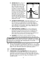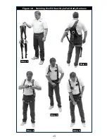
12
• A carabiner may be connected to a loop or ring connector that
is already occupied by a choker style connector. This type of
connection is not allowed for snap hooks.
2.4 CONNECTING SUBSYSTEMS:
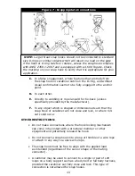
Connecting subsystems (self-
retracting lifeline, lanyard, rope grab and lifeline, cable sleeve)
must be suitable for your application. See section 1.1. See
subsystem manufacturer’s instructions for more information. Some
harness models have web loop connection points. Do not use
snap hooks to connect to web loops. Use a self-locking carabiner
to connect to a web loop. Ensure the carabiner cannot cross-
gate load (load against
the gate rather than
along the backbone
of the carabiner).
Some lanyards are
designed to choke onto
a web loop to provide a
compatible connection.
See Figure 8. Lanyards
may be sewn directly to
the web loop forming a
permanent connection.
Do not make multiple
connections onto one
web loop, unless choking
two lanyards onto a
properly sized web loop.
2.5 ANCHORAGE STRENGTH:
The anchorage strength required
is dependent on the application type. The following are the
requirements of ANSI 359.1 for these application types:
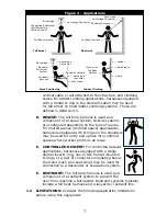
A. FALL ARREST:
Anchorages selected for fall arrest systems
shall have a strength capable of sustaining static loads
applied in the directions permitted by the system of at least:
1.
5,000 lbs. (22.2 kN) for non-certified anchorages, or
2.
Two times the maximum arresting force for certified
anchorages. When more than one fall arrest system is
attached to an anchorage, the strengths set forth in (1)
and (2) above shall be multiplied by the number of systems
attached to the anchorage.
B. RESTRAINT:
Anchorages selected for restraint and travel
restraint systems shall have a strength capable of sustaining
static loads applied in the directions permitted by the system
of at least:
1.
1,000 lbs. (4.5 kN) for non-certified anchorages, or
2.
Two times the foreseeable force for certified anchorages.
When more than one restraint and travel restraint system
is attached to an anchorage, the strengths set forth in (1)
and (2) above shall be multiplied by the number of systems
attached to the anchorage.
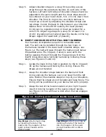
Figure 8 - Web Loop Connection
Insert lanyard web loop
through web loop or
D-ring on harness
Harness Web
Loop or D-ring
Web Loop on
Energy Absorbing Lanyard
Insert opposite end of lanyard through the
lanyard web loop
Pull the lanyard through the connecting web loop
to secure


