background image

4

INSTALLATION PROCEDURE

1.  MOUNT SIDE ARMS TO WALL
Note: For ground mount kits installation skip  
to step 1.4

1.1 

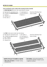
 Mark wall bracket positions and centres

. Refer 

to Figure 1 for fixing centres measurements for 
the model you are installing. The vertical distance 
between wall bracket mounting holes is 170mm. 
Take note of the recommended installation height.

1.2   

Use 8mm x 50mm masonry anchors or suitable 
wood screws to fasten to your selected surface. 

Consult a hardware store or builder if unsure.

1.3   

Drill holes suitable to your chosen fixings 
squarely into your wall at the marked location.

1.4  

 Fix the pre-assembled Side Arms to the wall. 

Note the Left and Right hand assemblies (Daytek 
logo should always be upright – refer to Fig. 1A)

2.   CONNECT CORNER BRACKETS 

AND FRONT BAR

1A

2A

2C

2E

2B

2D

2F

TO DETERMINE LEFT 

AND RIGHT  

PRE-ASSEMBLED 

SIDE ARMS ALWAYS 

ENSURE DAYTEK 

LOGO ON BRACKET 

IS UPRIGHT AND 

LINE BRACKETS ARE 

FACING INWARDS

2.1    

Attach a Corner Bracket over 
each end of the Front Bar and 
secure with the supplied nuts & 
bolts

 (See Fig. 2A – 2C). For Twin 

model, assemble and attach the 
Inner Front Bar first (shorter one).

2.2    

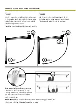
Lock each side arm into the 
upright position. 

To do this lift 

each side arm upwards to the 
maximum point of travel and push 
inwards until it hits a hard stop, then 
release (refer to operating diagrams 
on page 7).

2.3    

Install Front Bar to the Side Arms 
and secure with supplied nuts & 
bolts

 (See Fig. 2D – 2F).

Summary of Contents for MK2 MINI

Page 1: ...UCT MANUAL 100 Australian Owned Since 1954 daytek com au IMPORTANT READ THESE INSTRUCTIONS BEFORE USING YOUR CLOTHESLINE Suitable for models MINI SLIM SINGLE TWIN Product Code Date of purchase Name location of supplier FD1219 V3 ...

Page 2: ...ont Bar x 1 E Clothesline Cord F Nuts Bolts x 4 G Corner Brackets x 4 H Line Locking Cap x 4 I Spanner x 1 A Right hand Pre assembled Side Arm x 1 B Left Hand Pre assembled Side Arm x 1 C Front Bar x 1 D Clothesline Cord E Nuts Bolts x 4 F Corner Brackets x 2 G Line Locking Cap x 2 H Spanner x 1 浙江贝特日用品有限公司 BETTER HOME PRODUCTS Zhejiang CO LTD A E F D C B G H 浙江贝特日用品有限公司 BETTER HOME PRODUCTS Zheji...

Page 3: ... in fold down position Figure 1 Users Height 100mm 170mm Distance between mounting holes Tools required for installation Measuring tape and pencil Hammer Drill Socket set and adjustable wrench Hammer Scissors Hammer drill Spirit level MOUNTING LOCATION For best drying results select a location that receives maximum sunlight and airflow Ensure that the area has sufficient clearance around the cloth...

Page 4: ...embled Side Arms to the wall Note the Left and Right hand assemblies Daytek logo should always be upright refer to Fig 1A 2 CONNECT CORNER BRACKETS AND FRONT BAR 1A 2A 2C 2E 2B 2D 2F TO DETERMINE LEFT AND RIGHT PRE ASSEMBLED SIDE ARMS ALWAYS ENSURE DAYTEK LOGO ON BRACKET IS UPRIGHT AND LINE BRACKETS ARE FACING INWARDS 2 1 Attach a Corner Bracket over each end of the Front Bar and secure with the s...

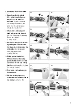
Page 5: ...ghten See Fig 3E 3F 3 3 Proceed to string the clothesline by locking the cord behind the line brackets at either side of the clothesline Use the diagrams on next page as a guide See Fig 3G 3H 3 4 Finish by inserting the line through the outer line clamp pulling tight hand tension only and secure with the Line locking Cap Be sure to work all of the slack line towards the end 3 5 Trim end of cord le...

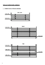
Page 6: ...6 3 STRINGING YOUR CLOTHESLINE CONTINUED START HERE FINISH HERE SINGLE START HERE FINISH HERE MINI SLIM FINISH HERE START HERE TWIN START HERE FINISH HERE INSTALLATION PROCEDURE CONTINUED ...

Page 7: ...tre of the Front Bar and gently lift the clothesline upwards to the maximum point of travel Pull outwards to unlock the bracket and lower Note Raising the frame without gripping the center may result in only one arm locking correctly If this occurs raise the affected arm to max height and press inwards until it hits a hard stop and release IMPORTANT Maximum recommended loading of this clothesline ...

Page 8: ...under law Where it is deemed necessary Daytek Australia will arrange for the inspection of your product Warranty exclusions Defects caused by incorrect installation adjustment modification overloading or misuse Paint deterioration caused by exposure to sea air where the product is installed in coastal areas Product damage or deterioration due to abnormal environmental conditions including storm da...

Reviews: