background image


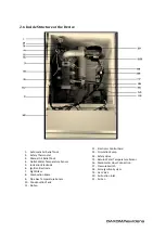
8 FIRST OPERATION 


Boiler Selection Knob 

Computer Connection Inlet 

Exit  

Reset 

Manual Control Knob 

Pipe Function Knob 

Confirm Button 

Set Button 

Information Button 

10  Operation Mode Selection 

Button 

11  LCD Display 

8.1 Heating Mode Selection 

When you press operation mode selection 
(number 10) knob, you can make passing 
between modes that are explained in the 
following. 
Modes are; 


OFF 


Concort Mode 


Night Mode 


Automatic Mode 


OFF: Device waits in standby mode. Except 
freezing prevention it does not operate any 
function.  
Comfort Mode:
 Operates according to set 
temperature.
 
Night Mode: Operates according to set 
temperature. 
Automatic Mode:
 Enables to operate depending 
hour time. General operation mode of the system 
will be this. 
 

 8.2 Setting Time Hour 


1-


It is entered to submenu by pressing 
confirm button (number 7) while it is in 
home screen of device. 

2-


It is entered to “Time program of heating 
cycle 1” menu by pressing OK button. 

3-


Firstly, it is chosen for which day’s 
program will make. You can make 
passing between options with Set Button 
(number 8). When you come to your 
demanded days, make your choosing 
with OK button. 
 

4-


Set the operation start hour and press 
the OK button.
   

5-


Then set operation finish hour and press 
OK button.
  

6-


Return to home screen by ESC button 
after you chose AUTO, your device will 
start to operate according to set 
operation hour. 


8.3 Room Temperature Setting 

While the device is in home screen, turn the 
number 8 button. Temperature values will be 
appearing at the display. Exit from menu with OK 
button after you bring your demanded value. 

8.4 Manual Using 

It is used for operating device independent from 
auto operation mode.
 Manual control can be 
activated or passivity with number 5 knob. 
Intended boiler temperature can be set from info 
menu.   

8.5 Reset 

When your device goes out of order, error 
description is written on the display and passes to 
standby mode. Do not forget that, this device can 
be gone out of order at gas leakage and 
installation failures.  After making control of 
these, try restart again by pressing number 4 
reset knob. After trying 3 times if the device has 
still not operated, contact with authorized 
service.


9. MAINTENANCE 

 
As well as it changes using place and using 
conditions, it is preferred to have your device 
maintenance done once a year. 
It is importantly preferred, have your boiler 
maintenance done by authorized service agency 
and using original parts while changing necessary 
parts. Do not forget that your device will be out 
of warranty in case of intervention of authorized 
personnel or using parts which are not original.   
It is needed to have your installation control 
made together with boiler maintenance for 
unproblematic operation of the system. 

Summary of Contents for Navidens 50

Page 1: ......

Page 2: ...AXOM boilers provide following sufficiency Gas Appliances Directive 2009 142 EEC Boiler Efficiency Directive 92 42 ECC Electromagnetic Compability Directive 2004 108 CE Low Voltage Directive 2006 95 C...

Page 3: ...3 1 Installation 12 3 2 Plumbing 12 3 3 Natural Gas Line 12 3 4 Electrical Installation 13 3 5 Pipe Line 13 4 SAMPLE INSTALLATION DIAGRAMS 15 4 1 Heating System with Boiler 15 4 2 Cascade Heating Sys...

Page 4: ...tric supply and gas inlet of the boiler If there is freezing risk at water installation or boiler system you need to discharge water inside the plumbing Control the operation of the air conditioner of...

Page 5: ...the device significant points that must be careful before operation of the system or during operation of system importance of periodic maintenance in terms of performance and efficiency of device and...

Page 6: ...2 4 Dimension of Device Navidens 50 70...

Page 7: ...Navidens 125 145 a Safety Valve Outlet b Plumbing Return c Gas Inlet d Plumbing Exit e Condensing Outlet f Cable Entry...

Page 8: ...2 5 Boiler Installation Distances...

Page 9: ...zation Electrode 6 Ignition Electrode 7 Sight Glass 8 Combustion Space 9 Pipe Gas Temperature Sensor 10 Condensation Tank 11 Siphon 12 Electronic Control Card 13 Circulation Pump 14 Safety Valve 15 Re...

Page 10: ...Partial Load 30 C 108 107 106 85 106 08 Nominal Heat Load 80 60 C 97 97 96 12 95 94 Min Heat Load 80 60 C 95 96 94 95 Efficiency Class Pipe Dates Pipe Pressure Pa 150 135 240 210 Exhaust Gas Flow Rate...

Page 11: ...e inch 3 4 3 4 1 1 Condensing Outlet mm 30 30 30 30 Safety Discharge Outlet mm 30 30 30 30 Fresh Air Inlet mm 125 125 150 150 Exhaust Gas Outlet mm 80 80 100 100 Specifications Cascade Connections 256...

Page 12: ...ing line flows from discharge Any blockage inside condensing line causes breakdown by failure of boiler Do not forget that this condition will be evaluated as out of warranty Be sure that plumbing is...

Page 13: ...rrespond with 2 meter pipe and 45 bend correspond with 1 5m pipe Do not forget that extra connection accessories that will be used for line will also create resistance and will reduce allowed total pi...

Page 14: ...Concentric Pipe System Double Pipe System...

Page 15: ...4 Sample Installation Diagram 4 1 Heating System with Boiler...

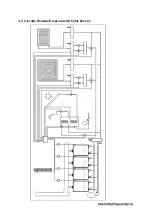
Page 16: ...4 2 Cascade Heating Diagram with Solar Energy...

Page 17: ...stance between them C33 Vertical exit is made from roof by interwoven pipes C43 Connection to common pipe outlet by interwoven pipes C53 Exit from wall or roof with separate pipes outlets at areas tha...

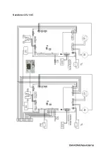
Page 18: ...6 ELECTRIC PROJECT Navidens 50 70...

Page 19: ...Navidens 125 145...

Page 20: ...Pressure Switch CS Pipe Gas Sensor TL Safety Thermostat M Fan Motor P Circulation Pump CLEMENS DESCRIPTION QX2 Boiler Cycle Pump QX3 Heating Cycle Pump H5 Room Thermostat B9 Outside Environment Senso...

Page 21: ...7 ACESSORIES PRODUCT DESCRIPTION PHOTO Cascade Communication Module Three Way Valve Connection Module Outlet Air Sensor Room Thermostat Cascade Sensor...

Page 22: ...100 150 mm 45 90 Degree Bends 80 125 mm 100 125 mm Exhaust Gas Pipe 80 mm 100 mm Additional Pipe 80 125 mm 100 125 mm Fresh Air Inlet Accessory 80mm 100mm For double pipes system Exhaust Gas Outlet A...

Page 23: ...reen by ESC button after you chose AUTO your device will start to operate according to set operation hour 8 3 Room Temperature Setting While the device is in home screen turn the number 8 button Tempe...

Page 24: ...sensitively By opening hot bulb seal between burner and heat exchanger must be controlled and if it is needed it must be changed Ignition and ionization electrodes must be cleaned by emery If it is n...

Page 25: ...ceeded 6 5 Heating cycle water pressure is too low 9 Bottom water pressure limit is reduced under1 10 Change battery of outside air sensor 6 18 Heating cycle water pressure 2 is too low 9 Bottom water...

Reviews: