background image


500151R04


DAVISCOMMS (S) PTE LTD 


Daviscomms Confidential  Page 

12 of 23 


2.3.1) RED LED (Charging Indicator) 

 Red LED constant on:  

 Li-ion battery is charging 

 Red LED off: Charging completed 

 
Charge the battery by plugging in power adapter connector into the power 
connector of the unit. Use power adapter with similar or better ratings to 
prevent damage to the power adapter. If not sure, use only power adapter 
provided in the package.  

2.3.2) GREEN LED (GSM Indicator) 

 Green LED constant on: Invalid SIM Card or SIM Card not detected 

 Slow  blink  (200ms  on  &  2s  off).  Device  has  found  GSM  network  & 

registered.  

Green LED Blinking: 

 Fast  blink  (200ms  on  &  600ms  off).  The  device  has  voice  or  data  line 

connected. 

2.3.3) Yellow LED (GPS Indicator) 


 Yellow LED constant on: GPS data valid. 

 Yellow LED off: GPS data invalid. 

2.3 LED indicators 


Summary of Contents for MTD1000

Page 1: ...500151R04 DAVISCOMMS S PTE LTD Daviscomms Confidential MTD1000 Evaluation Kit User Guide...

Page 2: ...MTD1000 9 2 3 LED indicators description 12 2 3 1 Red LED Charging Indicator 12 2 3 2 Green LED GSM Indicator 12 2 3 3 Yellow LED GPS Indicator 12 3 Interfacing the MTD1000 Evaluation kit for AT comma...
Page 3: ...urs It transmits the GPS data by using GPRS SMS For efficient data management it comes with a memory capacity of 6 000 full detail reports that include position date time system and input output ports...

Page 4: ...diameter hole each Adaptor Chargers for Europe or USA Model MTD1000 IE2N3F Embedded GPS antenna External GSM antenna Easy in vehicle mounting flange installation option Model MTD1000 EIDN3F Embedded...

Page 5: ...t Model number GPS GSM DC Jack Power connector With Without Tilt Sensor No of Input ports With Without Flow control MTD 1000 E I D N 3 F GPS E External GPS Antenna I Internal GPS Antenna GSM E Externa...

Page 6: ...2pin Option GPS Indicator GSM Indicator Charging Indicator GPS External Antenna Connector SMA option GSM External Antenna Connector SMA option Panic Button Option Mounting Flange Option 3 7V 780mAh L...

Page 7: ...UTSIDE NOTE RXD IS DATA OUTPUT FROM MTD1000 UNIT TXD IS DATA INPUT TO MTD1000 UNIT 2 1 6 3 7 4 8 5 9 D 9 FEMALE ON INTERFACE CABLE VIEW FROM OUTSIDE FOR CONNECTING TO PC RS232 PORT D 9 MALE D 9 Ports...

Page 8: ...MTD1000 device The receiver component required to receive GPS data to the MTD1000 device for a location fix iv RS232 standard 9 pin D female male connector cable The interface cable which connect the...

Page 9: ...er battery for MTD1000 An alternative solution to power up the MTD1000 without a power adaptor up to 24 hours Voltage current specification 3 7V 780mAh viii Evaluation PCB board For development purpos...

Page 10: ...d in package Connect the Li Polymer battery to the into the MTD1000 Note Do not use the internal Li Ion battery beyond standard operating temperature of 10C to 50C The MTD1000 can function directly fr...

Page 11: ...s Confidential Page 10 of 23 Step 3 Connect the GSM GPRS antenna to the GSM External Antenna Connector Screw in the SMA connector firmly Step 4 Connect the GPS antenna to the GPS External Antenna Conn...

Page 12: ...Daviscomms Confidential Page 11 of 23 Step 5 An example of the MTD1000 hardware setup with the 10 pin data harness cable RS232 for AT command communications and firmware flashing Recommended Connect t...

Page 13: ...similar or better ratings to prevent damage to the power adapter If not sure use only power adapter provided in the package 2 3 2 GREEN LED GSM Indicator Green LED constant on Invalid SIM Card or SIM...

Page 14: ...o create a hyper terminal connection from your PC to your device Step 1 On the Windows Start menu select Run The Run dialog appears The Windows Run Dialog Step 2 In the Open field type hypertrm exe an...

Page 15: ...an icon for the definition and click OK The Connect to dialog appears HyperTerminal Connection Description dialog Step 4 On the Connect To dialog select your primary COM port COM1 e g the example abo...

Page 16: ...ure the router or modem is powered on you are attached to the proper Com Port and verify your cabling is working Without these correct settings the device may display information but does not accept a...

Page 17: ...wer up the evaluation kit if only for AT commands communication to the MTD 1000 unit Configuring the jumpers requires the evaluation kit to be powered up by the external power adaptor 3 2 2 Full hardw...

Page 18: ...JUP 12 JUP 22 CTS 3 IN 3 0 V IN 2 5 V JUP 13 JUP 23 IN 6 8 01 0 V IN 4 5 V JUP 14 JUP 24 IN 7 10 02 0 V IN 3 5 V JUP 15 JUP 25 3 6 IN 5 0 V IN 6 5 V JUP 26 0 V IN 7 5 V JUP 27 0 V IN 5 5 V E g Enabli...

Page 19: ...IN2 are shorted JUP27 shorts PIN2 and PIN3 5 JUP23 JUP24 JUP25 and JUP26 are opened 3 2 2 2 3 output port option 1 JUP21 and JUP22 short PIN2 and PIN3 to make the Input Port 1 and Input Port 2 be pull...

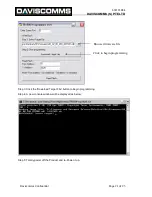
Page 20: ...nect serial cable from PC host to MTD1000 via the Communication Cable as mentioned in section 2 1 4 Step 2 Remove the internal battery and plug in the power source of The Product Step 3 Copy the whole...

Page 21: ...alue is 1 The programmer will set the COM port to the following settings COM Port Baud Rate 115200 bps Data Bits 8 Parity None Stop Bit 1 Flow Control None Step 2 Browse for the m0 file firmware file...

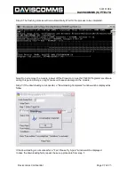
Page 22: ...dential Page 21 of 23 Step 3 Click the Download Target File button to begin programming Step 4 A new console window will be displayed as below Step 5 Totally power off the Product and re Power it up B...

Page 23: ...ower off the Product or close the TR 800 Programmer software during this period Doing so might cause unforeseen damage to the module Step 7 If the downloading is successful a Downloading Completed win...

Page 24: ...4 GPRS General Packet Radio Services GPRS is a packet based wireless communication service that promises data rates from 56 up to 114 Kbps and continuous connection to the Internet for mobile phone a...

Reviews: