


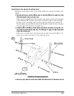


Mounting the Sensor Tilting Bracket
Page 3
M
OUNTING
THE
S
ENSOR
T
ILTING
B
RACKET
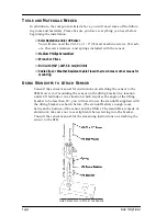
The instructions below explain how to select the correct tilt angle for the STB
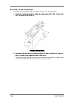
and how to mount STB on the Sensor Mounting Arm or on another surface.
The Tilt Angle
The STB allows you to angle the sensors between 0˚ and 66˚, depending on
which hole in the STB arms you use when mounting the bracket. The illustra-
tion below shows the orientation of the holes (from 1 to 16).
S
ENSOR
T
ILT
B
RACKET
A
RM
H
OLE
D
ESIGNATIONS
The table below shows the tilt angle achieved by using any given hole.
H
OLE
#
S
ENSOR
A
NGLE
H
OLE
#
S
ENSOR
A
NGLE
1
66.0˚
9
32.6˚
2
61.5˚
10
28.5˚
3
57.3˚
11
24.4˚
4
53.0˚
12
20.3˚
5
48.9˚
13
15.7˚
6
44.7˚
14
11.4˚
7
40.6˚
15
6.4˚
8
36.6˚
16
0.0˚


