background image

7

Power Up and Connect Your Gateway

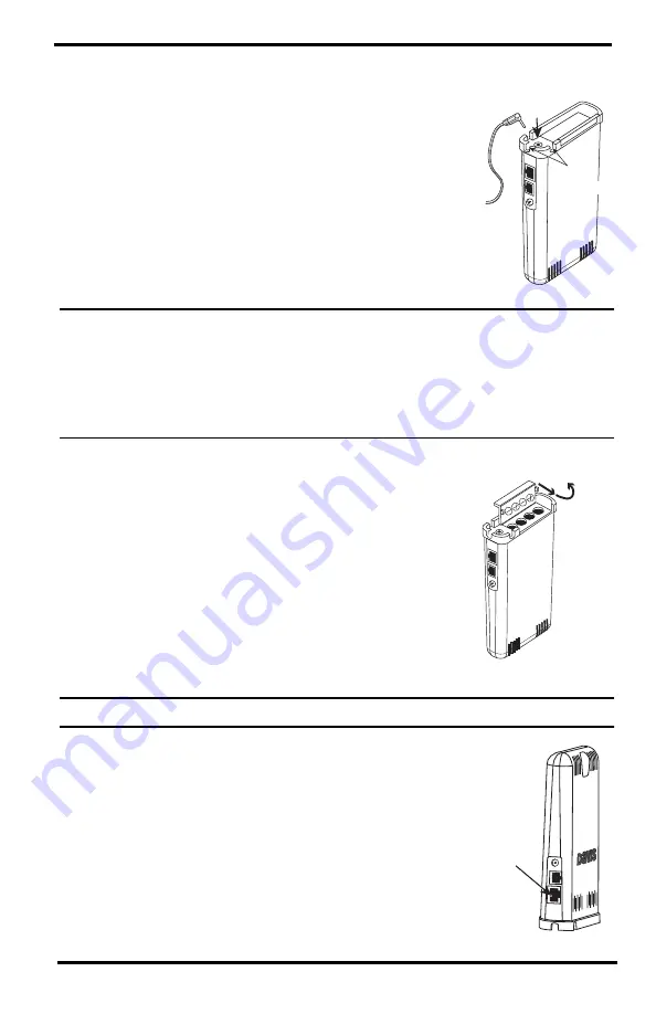
1. Plug the AC adapter into the socket on the bottom of 

the Gateway and plug the adapter into the wall.

There are cable channels to the front and back, as 
well as the side, in which to run the cable.

Note: 

The Gateway is powered by AC power with battery backup. 

AC power is required; 

it cannot be set up or run on batteries alone.

 It is highly recommended that you 

install batteries to prevent loss of data if AC power is lost. If AC power is lost, the 
Gateway will stop trying to upload data to WeatherLink.com, but it will continue to 
receive sensor data and store it. When AC power is resumed, it will reconnect with 
WeatherLink.com and send the records it stored during the outage to your database 
on the WeatherLink cloud.

2. Install the batteries. Open the battery 

compartment on the bottom of the Gateway. To 
do this, slide the cover forward then lift up.

Insert four AA batteries, making sure you insert 
them with the positive and negative ends oriented 
as indicated on the underside of the battery 
compartment cover.

3. If the IP Gateway on Wi-Fi, follow the prompts 

in the EnviroMonitor app to connect to Wi-Fi.

Note: 

You will need your Wi-Fi- password.

4. If you are connecting your Gateway via Ethernet, 

plug the included Ethernet cable into the socket 
on the Gateway. Connect the other end of the 
cable to your router. You will see a green light 
when the connection has been established.

5. The blue LED light will begin flashing indicating 

that the device is ready to connect to the 
smartphone app.

AC Adapter 

Socket

Cable 

Channels

Insert

4 AA

Batteries

To open, 
slide cover
forward 
then up.

Ethernet  

Cable 

Socket

Summary of Contents for EnviroMonitor 6805

Page 1: ...Product numbers 6805 and 6810 USER MANUAL IP Gateway and Node 3465 Diablo Avenue Hayward CA 94545 2778 USA 510 732 9229 www davisinstruments com...

Page 2: ...used for this transmitter must be installed to provide a separation distance of at least 20 cm from all persons and must not be co located or operating in conjunction with any other antenna or transm...

Page 3: ...tor Gateway and Nodes If you are just installing a Node and have already installed the Gateway you can skip to page 9 Set Up Nodes and Sensors Note Your IP Gateway is designed to be installed either i...

Page 4: ...higher they are mounted the longer the transmission distance The Gateway should be placed in a window or as close to the outside of the building and as close to the Nodes as possible higher is better...

Page 5: ...s should go Note If you are mounting the IP Gateway outside enclose it in a Universal Shelter product number 6618 SAMPLE FARM Vegetables Almonds East Almonds West Peppers H w y 1 0 Davis Rd Strawberri...

Page 6: ...of either two or more other Nodes or the Gateway and another Node A Node can even be installed simply to transmit data from more distant Nodes to the Gateway without any sensors installed in it By pl...

Page 7: ...quirements Tools Wi Fi or router Ethernet internet connection Wi Fi password Smartphone 4 AA batteries not included IP Gateway AC Adapter Blue LED Recessed Touch Pad External Antenna Connector Etherne...

Page 8: ...or app will guide you through creating an account on WeatherLink com adding the Gateway adding Nodes to the Gateway and adding sensors to the Node EnviroMonitor App EnviroMonitor App Guides you throug...

Page 9: ...r database on the WeatherLink cloud 2 Install the batteries Open the battery compartment on the bottom of the Gateway To do this slide the cover forward then lift up Insert four AA batteries making su...

Page 10: ...touch pad For the location of the recessed touch pad see the illustration on page 5 Contents of Gateway 6 The LED will turn solid blue when the Gateway has successfully connected to your smartphone 7...

Page 11: ...Panel Cable Mesh status LED Bluetooth status LED Solar Panel Jack Sensor Ports Internal Mesh Antenna Lithium Battery Battery Compartment Door Door Tabs Connector for Internal or External Antenna 1 4...

Page 12: ...en working outward to the Node furthest from Gateway This allows each Node to establish a connection with the Gateway or a Node that has already been installed Power up and Connect the Node Make sure...

Page 13: ...ifying information to the Node and allows its data to be received by the Gateway Having specific identification for each Gateway Node pair allows you to have multiple Gateways without cross transmissi...

Page 14: ...an RJ plug on its cable use the Davis RJ Adapter product number 6860 Or you can remove the plug and strip the wires Try not to strip the covering back so far that the bare wires can touch each other w...

Page 15: ...Hemisphere or north in the Southern Hemisphere Tip Mounting the Node may be easier if done by two people Mounting On a Fence Post or Pole Mount the Node onto a fence post or a pole with an outside di...

Page 16: ...range from Node to Gateway or Node to Node you may replace the internal mesh antenna with an external Long Range Antenna See page 17 Appendix A Using an External Long Range Antenna Manage Your Data Lo...

Page 17: ...are aligned properly and not offset Make sure the screws on the sensor adapters are very tight Make sure none of the sensor cables are pinched in the Node door If these steps don t solve the problem...

Page 18: ...Radio LED The radio LED has timed out to save power Close then open the door to activate the radio LED Radio LED is solid amber for 3 seconds when powering up The Node is powering up Radio LED is blin...

Page 19: ...on ranges of each of the antennas The antenna that comes installed in your Gateway or Node is a standard dipole If you need a longer cable for installation of the antenna use an Antenna Extension Cabl...

Page 20: ...a to seal the hole Then follow the steps below 1 Screw the antenna cable into the connector on the side of the IP Gateway 2 Use the EnviroMonitor app on your smartphone to set up the antenna In the ap...

Page 21: ...over tighten 4 Run the cable out the bottom of the Node making sure it exits against the foam 5 Close the Node shelter 6 Mount the antenna on a pole as high as possible using the mounting hardware inc...

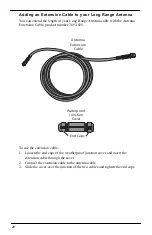
Page 22: ...product number 7692 025 To use the extension cable 1 Loosen the end caps of the weatherproof junction cover and insert the extension cable through the cover 2 Connect the extension cable to the anten...

Page 23: ...o 4670 m Update Interval 1 minute Weather Station Wireless Communications Range Line of Sight up to 1000 feet 300 m Through Walls 200 to 400 feet 60 to 120 m Node Operating Temperature 4 to 140 F 20 t...

Page 24: ...is ISO 9001 certified 3465 Diablo Avenue Hayward CA 94545 2778 U S A 510 732 9229 Fax 510 732 9188 info davisinstruments com www davisinstruments com Contacting Davis Technical Support For questions a...

Reviews: