Long Range RepeaterInstallation Addendum
For AC-Powered and Solar-Powered Long Range Repeaters
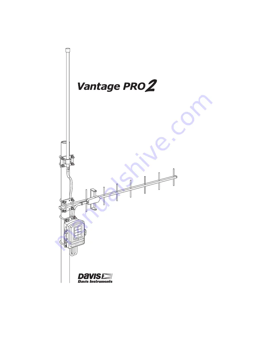
Models 7653 and 7654
Page 1: ...Long Range Repeater Installation Addendum For AC Powered and Solar Powered Long Range Repeaters Models 7653 and 7654...
Page 2: ...oes cause harmful interference to radio or television reception which can be determined by turning the equipment on and off the user is encouraged to try to correct the interference by one or more of...
Page 3: ...s intended to be used in conjunction with the Wireless Repeater Installation Manual The table below shows the location of the information required to install and maintain your Long Range Repeaters Sec...
Page 4: ...has the following contents Transmitter DIP Switches Repeater DIP Switches Repeater Test Switch TX LED Status LED Battery Compartment Solar Power Tab Receiving Antenna Cable AC Adapter Transmitting Ant...
Page 5: ...or transmitting the data to another repeater or receiver The two exter nal antenna choices are Omni direction Yagi directional antenna You must purchase external antennas appropriate to your network a...
Page 6: ...er and receiver proportionally All wireless Davis Instruments stations and standard wireless repeaters come equipped with standard dipole antennas that have an omni directional radiation pattern To de...
Page 7: ...istance you should use to determine the antenna distances and which antennas would best suit the needs and dis tances in your network Use the following multiplier matrix to determine the antenna relat...
Page 8: ...ented in a sam ple antenna configuration Antenna Topology Legend Antenna Symbol Antenna Type Vantage Pro2 Console Weather Envoy Vantage Pro2 Wireless Repeater Any Vantage Pro2 Station Omni directional...
Page 9: ...omni antenna The transmitting Yagi antenna is sending the data packets to Repeater B The receiving antenna on Repeater B is an omni antenna that is collecting data from not only repeater A but also f...
Page 10: ...8 A C ISS Station Temperature Station Leaf Soil Station B D Soil Temperature Station Console Transmitting Receiving Representitive Antenna Configurations...
Page 11: ...peater enclosure Omni and Yagi Antenna Combination Assembly The omni and Yagi combination assembly should be performed from the bottom antenna Yagi up to the top antenna Omni so that the omni antenna...
Page 12: ...nna s communication 10 While holding the omni antenna against the pole place a U bolt around the pole and through the two holes at the top and of the antenna plate 11 Place a flat washer a lock washer...
Page 13: ...the nuts 13 Place the second U bolt around the pole and through the two holes at the bottom of the shelter Installing a Repeater on a Pole Refer to the following illustrations to install the repeater...
Page 14: ...grommet For identification purposes the transmitting antenna cable should be threaded through the grommet on the left side and the receiving cable on the right side to align with the antenna cable co...
Page 15: ...Draw 1 5 mA at 4 6 VDC average draw when not in Test Mode Batteries CR 123A 3 volt lithium battery Battery Life Estimates with no solar or AC power input Both received directly by the repeater and tho...
Page 16: ...t up to 2 miles 3 km Wireless Communication OV EU UK models Transmit Receive Frequency 868 0 868 6 MHz FHSS Frequency Hopping Spread Spectrum ID Codes Available 8 Output Power 868 0 868 6 MHz FHSS CE...