Datwyler IPDU-A Series User Manual Download Page 5


IPDU-A Series User Manual     


5

. Hardware introduction


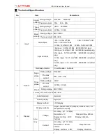
1. Front panel introduction:   

Panel 

composition 

Function 

Description 

RUN 

Run indicator 

States: flash frequency is 1 second   

KWH 

kWh indicator 

States: flash frequency depends on the load 

ALM 

Alarm indicator 

Sates: light on if there is an alarm happening 

NET 

Ethernet port 

LAN/WAN Ethernet communication port 

SER 

Daisy-chain port 

RS-485 daisy-chain communication port 

LINK 

Daisy-chain port 

RS-485 daisy-chain communication port 

MENU 

Menu key 

To view the LCD Module displayed information, light up the LCD 

Module background, save the configuration as ENTER key.   

Restore to factory settings: Hold the MENU key and press the 

RESET button to restore 

Mute alarming: Press and hold the MENU key for 4 seconds to 

turn On/Off the alarm 

UP 

Function set key; 

light up the LCD Module background, set the Master or Slave 

address cord, the maximum threshold of voltage, current, 

temperature and humidity from 0 to 9 

DOWN 

Position 

selection key 

light up the LCD Module background, to select the address cord, 

maximum threshold of voltage , current, temperature and humidity   

RESET 

Restart button 

Restart the device 

Screen 

View the states 

display the power and environment data 

T/H 

Temperature and 

humidity sensor 

port 


2

Initialization 

When power on, the RUN indicator will flash and the PDU works normally after initializing the LED indicator 

and  TFT  screen.  Following  is  the  LCD  displaying  content  introductions  for  the  Direct  Current  Module

AC 

single phase module and AC three phase module:   


2.1 Direct Current module:   

1st screen: Amps (0.1A), Voltages (220VDC), Power (0.0kW), kWh (0.0kWh) (Figure 1) 

2nd screen: the temperature and humidity date (figure 2) 

3rd screen: the baud rate (4800/9600/19200/38400) (Figure 3) 

4th screen: the device IP, address code (from 0 to 4) (Figure 4) 

5th screen: the threshold of the current (32A) and voltage (276VDC) (Figure 5) 

Summary of Contents for IPDU-A Series

Page 1: ...IPDU A Series User Manual 1 IPDU A Series User Manual ...

Page 2: ... 3 Applications Ⅳ 3 Product sketch Ⅴ 4 Mounting method Ⅶ 4 Hardware introduction Ⅷ 5 1 Front panel introduction 5 2 Initialization 5 3 Hardware settings 7 4 Daisy chain connection 8 Software introduction Ⅸ 9 1 Web browser access 9 2 SNMP access 14 3 Telnet access 16 Technical Specification Ⅹ 17 ...

Page 3: ...logy Main functions Ⅱ 1 Monitor input voltage 2 Monitor total load current 3 Monitor total power kW 4 Monitor energy consumption kWh 5 Monitor the micro environment in the cabinet Monitoring method Ⅲ User can access the IPDU A Series through WEB interface SNMP v1 or Telnet command console IPDU A Series can be also monitored and managed through centralized management software CLEVER Manager Applica...

Page 4: ...e GND 2 Orange GND 3 Green White RS485 A 4 Blue RS485 A 5 Blue White RS485 B 6 Green RS485 B Brown White GND 8 Brown GND 1 Screen TFT screen 2 RUN Run indicator KWH kWh indicator ALM Alarm indicator 3 NET Ethernet port 4 SER Daisy chain port 5 LINK Daisy chain port 6 MENU Menu Key 7 UP Function set key 8 DOWN Position selection key 9 RESET Restart button 10 T H Temperature Humidity sensor port 2 3...

Page 5: ...nd set the Master or Slave address cord the maximum threshold of voltage current temperature and humidity from 0 to 9 DOWN Position selection key light up the LCD Module background to select the address cord maximum threshold of voltage current temperature and humidity RESET Restart button Restart the device Screen View the states display the power and environment data T H Temperature and humidity...

Page 6: ...L1 Amps 0 1A Volts 220VAC Power 0 0kW kWh 0 0kWh Figure 1 2nd screen L2 Amps 0 1A Volts 220VAC Power 0 0kW kWh 0 0kWh Figure 2 3rd screen L3 Amps 0 1A Volts 220VAC Power 0 0kW kWh 0 0kWh Figure 3 4th screen the temperature and humidity date figure 4 5th screen the brad rate 4800 9600 19200 38400 Figure 5 Figure 1 Figure 2 Figure 3 Press MENU Press MENU Figure 1 Figure 2 Figure 3 216VDC 00 0A 00 0K...

Page 7: ... 3 2 Current or Voltage threshold settings To locate the threshold setting page like L1 32 0A 276VAC Press DOWN key to select the value need to be set the select position will flesh then press UP key to set the threshold value the allowed maximum current is 32A and maximum voltage is 276VAC Note All above settings must be saved by pressing the MENU key and the settings will take effective after th...

Page 8: ...the screen When the alarm was turned off an F in red will be displayed in the screen 4 Daisy chain connection Serial Daisy chain mode Figure 1 4 1 Setting one IPDU A Series as Master unit and the rest as Slave unit The maximum daisy chain is 4pcs Apply to IPDU A Series 6 refer to figure 1 Ethernet Daisy chain mode Figure 2 4 2 Connect the each PDU to the port from the HUB and connect the Net port ...

Page 9: ...l the IPDU A Series by web browser like Internet Explorer google chrome and etc by input the correct IP address in the address bar The pop up login window is illustrated as figure 1 Figure1 User will see the home page as figure 2 after entering the correct user name and password in the login dialog box Figure 2 Main interface includes 3 parts Company Logo Menu and device states Company Logo MENU ...

Page 10: ... or Slave units One Master unit can support to you 4 Slave unit Slave 1 Slave 4 B Threshold setting to set threshold of total load current See below User can set up the threshold of current voltage temperature and humidity from the threshold settings page as figure 3 Figure 3 Set up the threshold of current voltage temperature and humidity The current of single phase range from 0 63A three phase r...

Page 11: ...ice name customer wants to define in the blank then save it Web server port Work model Revise master and slave mode to set slave1 2 Virtual Value 1 4 b Energy Setting Clear energy line1 Click button The same operation for Line 2 and Line3 in 3phase products Figure 4 D User settings as figure 5 Figure 5 ...

Page 12: ...ddress is correct so that email can be sent out Note Restarting software is necessary after a modification of the network settings F SNMP Setting see below figure 7 The default get community and Set community is public and private User can modify according to the specific application Fill in the trap address of SNMP management platform trap alarm will be sent automatically There are 2 Trap address...

Page 13: ...mail Alarm Settings as figure 8 Set the SMTP including SMTP account password SMTP server and port then save Click Testing and fill in the testing email address If the test email is received the setting is effective See below interface Figure 8 ...

Page 14: ...ltage of L1 for master device mVoltage B 1 3 6 1 4 1 30966 10 3 2 2 Voltage of L2 for master device mVoltage C 1 3 6 1 4 1 30966 10 3 2 3 Voltage of L3 for master device mCurrent A 1 3 6 1 4 1 30966 10 3 2 4 Current of L1 for master device mCurrent B 1 3 6 1 4 1 30966 10 3 2 5 Current of L2 for master device mCurrent C 1 3 6 1 4 1 30966 10 3 2 6 Current of L3 for master device mEnergy A 1 3 6 1 4 ...

Page 15: ... 25 Voltage of L3 for slave 2 sTwoCurrent A 1 3 6 1 4 1 30966 10 3 2 26 Current of L1 for slave 2 sTwoCurrent B 1 3 6 1 4 1 30966 10 3 2 27 Current of L2 for slave 2 sTwoCurrent C 1 3 6 1 4 1 30966 10 3 2 28 Current of L3 for slave 2 sTwoEnergy A 1 3 6 1 4 1 30966 10 3 2 29 Power energy of L1 for slave 2 sTwoEnergy B 1 3 6 1 4 1 30966 10 3 2 30 Power energy of L2 for slave 2 sTwoEnergy C 1 3 6 1 4...

Page 16: ... 3 2 53 Power energy of L3 for slave 4 sFourTem 1 3 6 1 4 1 30966 10 3 2 54 The temperature value of Slave 4 sFourHum 1 3 6 1 4 1 30966 10 3 2 55 The temperature value of Slave 4 3 Telnet access The application of Telnet enable the user to remotely manager the PDU easily The user can monitor and manage the device by entry the command line from the Telnet program Telnet require the the customer ter...

Page 17: ...l plug 3 16A input 5 2 5 mm2 3M IEC60309 industrial plug 3 32A input 5 6 mm2 3M IEC60309 industrial plug Overload protector Circuit breaker optional 2 Output Single phase Rating voltage 110 220V The max current 16A 32A 63A Three phase Rating voltage 220V The max current 3 16A 3 32A Direct current Rating voltage 240V 336V The max current 40A 60A Outlet standard Optional Outlet quantity Optional 3 D...

Page 18: ...MP v1 Network IP gateway subnet mask DNS 9 Alarm System default alarm When current exceed Max When voltage exceed Max User defined alarm When current exceed the threshold When voltage exceed the threshold When Temperature humidity exceed the threshold Alarm Buzzer sounds Send E mail to administrator automatically SNMP sends trap alarm information 10 Central management Compatible with CLEVER Manage...

Reviews: