UK
DATEQ SPL-D3 manual
Installation
7
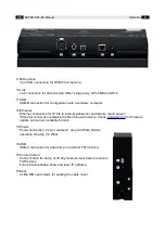
USB port; USB-A female
Pin
Function
Description
1 VCC +
Supply
2 Data –
Data
3 Data +
Data
4 GND
Ground
Table 4: USB connections
Link;
Jack 3-pens female
Pin
Function
Description
SL Ground
Data ground
Tip Data TX
Data send
Ring Data RX
Data receive
Table 5: Display link connections
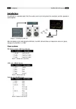
Microphone input
Connect the supplied measuring microphone here. The wiring of the microphone can be
lengthened with standard microphone cable. Pay attention to the polarity of the wiring. If
the microphone is wrongly connected it won't work. The limiter will give an error message,
and the volume will be extremely reduced.
The microphone should be installed so that it 'hears' both sound from the speakers as well
as the sound from the crowd in the room. The microphone can be placed closer to the
speakers when the maximum allowed level is very low. This reduces the effects of
background noises.
Link
This is the data connection with the optional SPL-5MK2, SPL6 or SRL1 stage relay. For this a
stereo 6.3mm jack cable is required.
Summary of Contents for SPL-D3
Page 1: ...SPL D3_200101_V1 0EN SPL D3 Multi Color Display Sound level logger Manual ...
Page 12: ......
Page 13: ...SPL D3 Multi Color Display Sound level logger Configuration ...
Page 14: ...Notes ...
Page 24: ...24 Installation DATEQ SPL D3 manual UK ...


