background image


40 


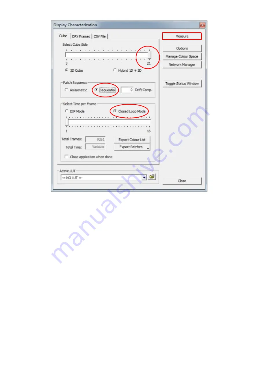
Click the 

Measure

 button, the 

Calibration Status

 window will appear along with the 

Calibration 

Area 

and


a dialogue box. Drag the 

Calibration Area

 onto the TLM-170F. Lastly, enter a name for 

this particular calibration in the dialogue box, point the probe at the calibration area as close as 
possible then click the 

OK

 button to start calibration. 

Please note that it takes approximately one 

hour to perform 9261 point measurements

.  

Summary of Contents for TLM-170F

Page 1: ...17 SCOPEVIEW PRODUCTION MONITOR Instruction Manual TLM 170F TLM 170FM TLM 170FR...

Page 2: ...PICTURE 17 Brightness 17 Contrast 17 Saturation 17 Tint 17 Sharpness 17 HDMI RGB Range 17 HDMI EDID 17 Color Space 17 Camera Log 18 Def Log 18 User Log 18 Gamma 18 HDR 19 Back Light 19 Color Temperatu...

Page 3: ...ces The information offered in this instruction manual is intended as a guide only At all times Datavideo Technologies will try to give correct complete and suitable information However Datavideo Tech...

Page 4: ...from the type of power source indicated on the marking label of the AC adapter If you are not sure of the type of power available consult your Datavideo dealer or your local power company 8 Do not all...

Page 5: ...cident misuse unauthorized repairs sand grit or water is not covered under warranty Viruses and malware infections on the computer systems are not covered under warranty Any errors that are caused by...

Page 6: ...nserve natural resources and ensure that it is recycled in a manner that protects human health and the environment For more information about where you can drop off your waste equipment for recycling...

Page 7: ...t and field production applications Features DCI 4K 60p and UHD 4K 60p videos for both input and output 17 monitor with FHD 1920 x 1080 LCD display Supports column YRGB peak time code waveform vector...

Page 8: ...F SDI Button Press once to enable the SDI video source on the monitor screen You can connect the loop thru port see Rear Panel to a monitor to view the activated input video source As the SDI video so...

Page 9: ...enu or increase decrease parameter values using the audio volume adjustment buttons While NOT in the OSD menu pressing either one of the audio volume adjustment buttons will open a Volume slide bar at...

Page 10: ...shortcut key selected at step 1 4 Press the EXIT button to close the pop up function list The pop up function list is shown below Center Marker Aspect Marker Safety Marker Overscan Scan Aspect Color S...

Page 11: ...SDI and HDMI inputs HDMI Input 1 2 Connect HDMI video and audio source devices HDMI 1 YUV420 not supported HDMI 2 YUV420 supported USB 2 0 Port SERVICE For firmware upgrade only see Firmware Update f...

Page 12: ...ns Sub Options Parameters Picture Brightness 0 100 Contrast 0 100 Saturation 0 100 Tint 0 100 Sharpness 0 100 HDMI RGB Range Full Limited HDMI EDID 2K 4K Color Space DCI P3 EBU Rec709 SMPTE C Native C...

Page 13: ...100 Color Temperature 3200 K 5500 K 6500 K 7500 K 9300 K User Color Red Gain 0 255 Green Gain 0 255 Blue Gain 0 255 Red Offset 0 511 Green Offset 0 511 Blue Offset 0 511 Marker Center Marker ON OFF C...

Page 14: ...Mat OFF 1 2 3 4 5 6 7 Thickness 1 2 3 4 5 6 7 8 9 10 11 12 13 14 15 User Marker H1 1 3840 User Marker H2 1 3840 User Marker V1 1 2160 User Marker V2 1 2160 Function Scan Zoom Aspect Pixel to Pixel As...

Page 15: ...0 20 10 Freeze OFF ON Waveform Waveform Multi Y YCbCr RGB OFF Vector OFF ON Transparency 50 25 OFF Peaking OFF ON Peaking Color Red Green Blue White Black Peaking Level 0 100 False Color OFF Default S...

Page 16: ...2 CH 3 4 CH 5 6 CH 7 8 CH 9 10 CH 11 12 CH 13 14 CH 15 16 Audio Left Out CH1 16 SDI CH 1 8 HDMI Audio Right Out CH1 16 SDI CH 1 8 HDMI System Language English Traditional Chinese Simplified Chinese Co...

Page 17: ...PC Monitor RGB Limited 16 235 Standard or HD TVs HDMI EDID The EDID learning function is only used when you experience any failures in playing audio and video correctly You will be able to force the...

Page 18: ...rom the list below SLog2ToLC 709 Sony Log format to Rec709 SLog2ToLC 709TA SLog2ToSLog2 709 SLog2ToCine 709 SLog3ToLC 709 SLog3ToLC 709TA SLog3ToSLog2 709 SLog3ToCine 709 ArriLogCTo709 Arri Log format...

Page 19: ...HDR transfer function Back Light Adjust the back light level from 0 100 Color Temperature Select a color temperature for your scene Color temperatures available on the TLM 170F are listed as follows 3...

Page 20: ...e can be set to small medium or large Aspect Marker Sets the aspect marker display at the aspect ratio selected from the list below OFF 16 9 1 85 1 2 35 1 4 3 3 2 2 0X 2 0X MAG Grid User Safety Marker...

Page 21: ...e moves the marker down Function This allows the user to set advanced settings for the TLM 170F such as the scan mode the aspect ratio underscan mode H V delay check field zoom and etc Details of how...

Page 22: ...rendered on the display will be larger than the physical area of the screen creating a cropped image on the monitor screen H V Delay Used to monitor the blanking area for H sync and V sync In H delay...

Page 23: ...sting the brightness contrast saturation tint and sharpness Zoom The zoom function allows you to enlarge the image by a certain percentage 10 90 Note Zoom control is disabled if the scan mode is set t...

Page 24: ...evel Hue The color markers are red magenta blue cyan green and yellow The proximity a signal to one of the markers tells you what color it is Saturation A vectorscope shows you how saturated your colo...

Page 25: ...Opaque Peaking filter The peaking filter once enabled will place color lines on edges of the subject of the focus in the image This function works well if the subject of the focus is correctly exposed...

Page 26: ...rnal equipment To best utilize this feature you must first understand the color chart below The color chart is like a color scale The exposure level is represented by different colors which correspond...

Page 27: ...yellow and finally to red if overexposed Blue indicates underexposure An example of an original image with the false color applied is shown on the left of the image below The four available false col...

Page 28: ...l be able to see a zebra pattern superimposed over parts of the image that are exposed to a specific level In this way the exposure of the image displayed on the screen can then be adjusted accordingl...

Page 29: ...ight than it is to blue or red light Finally the luminosity histogram is produced by counting how many pixels are at each brightness level as shown in the diagram below RGB The RGB histogram is a grap...

Page 30: ...d throughout an image allowing you to evaluate the brightness and exposure of that individual color channel See the diagram below for an example of the color histogram Time Code The TLM 170F is able t...

Page 31: ...MI mode there will be 8 HDMI embedded audio channels Audio Vector Enable the audio vector scope shown below to view the audio information Audio Vector CH HDMI First enable the audio vector scope then...

Page 32: ...ct color calibration 7 Switch the standby power mode 8 Reset the entire device s settings Language The available languages are English Traditional Chinese and Simplified Chinese Color Bar Available op...

Page 33: ...s LightSpace Color Management System CMS which includes a calibration probe and the CMS software The TLM 170F works with CAL PRO and XPT versions only Visit https www lightillusion com lightspace htm...

Page 34: ...CMS software for color correction Device Setup 1 Before starting the calibration process you need to install and register the CMS software first Copy and paste the link https www lightillusion com co...

Page 35: ...o OEM colourimeter Click the link https www lightillusion com murideo_six g html to purchase 4K 8K signal generator Please note that the signal generator is optional 2 Connect the calibration device t...

Page 36: ...0 minutes You can start color calibrating your monitor after you ve completed the device setup Software Setup 1 Select the connected Probe Follow the path Tools Discoverable Probes to access the color...

Page 37: ...obe and a dialogue box with the message Do you want to connect to i1 Display Pro should pop up Note If the probe model is CA 310 you should see the corresponding model number in the message Click OK i...

Page 38: ...MS User Interface click Tools Calibration Calibration Interface to open the Calibration Interface window then click the Options button to open the window below Locate Patch Scale pane circled in red i...

Page 39: ...t the probe at the calibration area as close as possible then click the OK button in the dialogue box to start calibration Repeat the process until the MAX value in the Luminance Units pane is in the...

Page 40: ...ue box Drag the Calibration Area onto the TLM 170F Lastly enter a name for this particular calibration in the dialogue box point the probe at the calibration area as close as possible then click the O...

Page 41: ...rce pane select Rec709 for the color space and in the Destination pane select the color space generated in the previous step In the Name textbox enter the name of the 3D cube color calibration file Th...

Page 42: ...select the 3D DaVinciResolve33 cube format Lastly click the Export button to export the 3D Cube file to a USB thumb drive Settings and file exports of the DCI P3 and BT2020 color spaces are depicted...

Page 43: ...Insert the USB thumb into the SERVICE port of the TLM 170F and you will be prompted whether to write the 3D CUBE file to the monitor Select Yes to write the 3D Cube file to the monitor The color cali...

Page 44: ...Drive Max 16GB USB A Cable To update the TLM 170F firmware MCU 1 Unzip extract the firmware file 2 Rename the bin file to mcu bin 3 Format the USB 2 0 pen drive to FAT32 4 Copy mcu bin to the USB 2 0...

Page 45: ...2 0 pen drive into the USB 2 0 port labelled SERVICE on the back of the monitor 5 Load FPGA appears on the screen as soon as the TLM 170F detects the fpga bit file 6 fpga bit is automatically loaded...

Page 46: ...46 6 Dimensions mm...

Page 47: ...inal Pitch 5 08mm Standard SDI Signal Format 4096x2160p 23 98 24 25 29 97 30 50 59 94 60 3840x2160p 23 98 24 25 29 97 30 50 59 94 60 4096x2160Psf 23 98 24 25 29 97 30 3840x2160Psf 23 98 24 25 29 97 30...

Page 48: ...48 General Operating Temperature 0 C to 40 C 32 F to 104 F Storage Temperature 20 C to 60 C 4 F to 140 F Humidity 10 to 80 non condensing Dimension mm 403 L 305 W 36 6 D Weight 4 1 Kg...

Page 49: ...49 Notes...

Page 50: ...50 Notes...

Page 51: ...51 Notes...

Page 52: ...ervice and Support www datavideo com product TLM 170F www datavideo com product TLM 170FM www datavideo com product TLM 170KR Datavideo Technologies Co Ltd All rights reserved 2020 Feb 11 2022 Version...

Reviews: