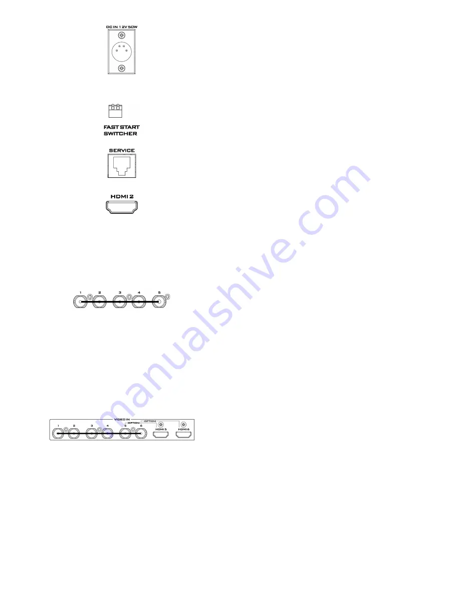
Datavideo HS-2200 Quick Start Manual Download Page 7


7


DC Input 

Connect the supplied 12V 5A PSU to this 4pin XLR socket.  
 
Pin 1 = GND ( - ) 
Pin 2 = NC 
Pin 3 = NC 
Pin 4 = VCC ( + ) 


Mini Switch 2 

Firmware upgrade switch (The two DIP switches must be set to 
the UP position). 


Service Port  

This RJ45 Ethernet port is used for updating the HS-2200 
firmware, or uploading logo image. 


HDMI Multi-View Outputs 

HS-2200 is capable of achieving multi-view monitoring by 
connecting multi-view monitor to the HDMI port. The HDMI output 
can be used for monitoring video and audio in a number of 
different configurations.  
 
The HDMI connectors are located on the rear panel.  
 

Note: 

HDMI multi-view output format is 1080i. 


SDI Video Outputs 

The five BNC output connectors are user defined SDI outputs. 
Each of these SDI outputs has the option to be: 
 
1. Program 
2. Program logo free 
3. Program logo & titles free 
4. Preview 
5. Aux1,2,3 or 4 
6. Multi screen 
 

Note: 

Please enter the HS-2200 MENU to set the 

OUTPUT 

SOURCE


Video Input Modules 

The HS-2200 is equipped with six video input channels.  
 
Video Input set is comprised of six SDI connectors and two HDMI 
ports. The last two channels (#5 and #6) can be switched between 
SDI connector and HDMI port, i.e. the user is allowed to use CH5 
and CH6 for either a SDI source or an HDMI source. 
 

Note: 

The CG (picture and animation) data source via 

HDMI cable connect to the HS-2200 channels 5 and 6. 
Can edit CG function from the PC. 


Note:

 Please enter the HS-2200 MENU to set the input 

source for 

INPUT 5 AND 6 MODE


Summary of Contents for HS-2200

Page 1: ......

Page 2: ...2200 Video Layers 25 Picture in Picture Function 26 PIP Settings 26 PIP Preset and PIP Program 26 Assigning a video source input to a PIP 26 DSK Function 27 AUDIO Function 28 AUDIO FOLLOW VIDEO 29 AU...

Page 3: ...at the total of the ampere ratings on the products plugged into the extension cord do not exceed the extension cord s rating 10 Make sure that the total amperes of all the units that are plugged into...

Page 4: ...Warranty providing the product is registered with Datavideo within 30 days of purchase For information on how to register please visit www datavideo tek com or contact your local Datavideo office or...

Page 5: ...ni Switch 2 4 TO BELTPACK 13 Ethernet Port for Load File Firmware Updates 5 3pin XLR Audio Inputs 1 4 14 Multi View Outputs HDMI 6 MONITOR F W Upgrade 15 Video Output 1 5 HD SDI 7 3pin XLR Audio Outpu...

Page 6: ...rts four channels XLR Balanced Audio Input MONITOR F W Upgrade Socket is for monitor F W upgrade AUDIO Outputs Supports two channels XLR Balanced Audio output Console Port This 9pin D Sub connector is...

Page 7: ...080i SDI Video Outputs The five BNC output connectors are user defined SDI outputs Each of these SDI outputs has the option to be 1 Program 2 Program logo free 3 Program logo titles free 4 Preview 5 A...

Page 8: ...nt 15 Cut Auto Take 5 Audio Follow Video 16 Mix Function 6 Menu Control 17 Freezes Function 7 Transition Selection 18 T Bar 8 F1 F4 TBD 19 Program Row 9 PIP Selection PVW PGM 20 Preset Row 10 DSK Sele...

Page 9: ...colour bars for use on the Program and Preset row Note Please into the HS 2200 MENU selects CONSOLE SETTINGS to setting the background colour MSCR PGM Switch the Multi Screen view or Program view Note...

Page 10: ...the XPT VIDEO button press the required input on the Preset row 4 The input button will flash to confirm the audio source is selected XPT Audio Assigning audio source channel setting depended on your...

Page 11: ...Top Box Wipe from outside edges to Centre Box Wipe from Centre to outside edges Upper Left corner Wipe to Lower Right corner Upper Right corner Wipe to Lower Left corner Lower Left corner Wipe to Uppe...

Page 12: ...1 and LOGO 2 buttons are used to display pre selected logos on the HS 2200 Preview and Program outputs When the button is active the selected logo is shown These logos are selected from the switcher s...

Page 13: ...which are chosen by a menu option TIMER In some mixing or switching applications it is useful to have a countdown timer It could be that the input is a pre recorded video clip and you need to know whe...

Page 14: ...2000L or Monitor 6 3mm Stereo Headphone Socket for conventional headphones Headphone Volume Control Controls Headphone or Headset volume level Use the Headphone section to accurately monitor any of th...

Page 15: ...ation with all channels All channels will hear communication from the operator or from any other channel using the TALK button Channel Buttons 1 8 Opens communication with individual channels More tha...

Page 16: ...OOM This feature is designed for use with HD SDI and HDMI sources above 720p resolution Press this button to zoom in to the video on the display This is strictly a zooming function and does not alter...

Page 17: ...ION I SPECIAL FUNCTION II SETUP F W FACTORY RESET AUDIO CONTROL EXIT MAIN ADJUST You can choose BRIGHTNESS 0 100 CONTRAST 0 100 SHARPNESS 0 100 SATURATION 0 100 TINT 0 100 BACK LIGHT 0 100 NR HIGHD MI...

Page 18: ...T COLOR RED GREEN ORANGE WHITE EDIT TITLE A Z EXIT SETUP F W You can choose UPDATE SCALER F W SCALER VER UPDATE FPGA F W FPGA VER EXIT See Monitor firmware update procedure section page 19 for more de...

Page 19: ...E on the rear of the TLM 170P monitor 5 Power the monitor on and press the MENU button to display the OSD Main Menu 6 Using the OSD Menu buttons UP DOWN ENTER highlight and select the SETUP F W option...

Page 20: ...1080i 720p SD 4 3 SD 16 9 The Video can be changed to the desired standard Brightness Range 072 to 184 Contrast Range 36 to 92 Saturation Range 36 to 92 Aperture 0 3 Y C Delay 0 3 Video Settings Set t...

Page 21: ...Clock Settings Clear Seconds DSK On Off Luma Key Mode On Off 10 DSK Settings Luma Key Level Luma Key Level 0 black to 255 white Width 0 4 11 Wipe Border Settings Wipe 1 17 Color 1 8 Multi Screen Mode...

Page 22: ...Video standard 1 Mode 1080i 720p SD 4 3 SD 16 9 The Video can be changed to the desired standard 3 Into HS 2200 Main Menu to setting Video input 6 on HDMI SDI HDMI RGB YUU_422 3 Input 5 and 6 Mode Inp...

Page 23: ...the icon to install CG 200 Software Step2 Step by Step install the CG software to finish Step3 When finished please double click the icon to execute the software 6 Enter the Settings into Preferences...

Page 24: ...24 7 Select DEMO file to play the CG data the video standard must the same as HS 2200 8 Set HDMI output to the ON 9 Enter Play all to enable CG function...

Page 25: ...s when enabled In some setups the PIP 1 image can hide the PIP 2 image Change the position or size of the PIP 2 or PIP 1 image if required The DSK layer can occupy the whole screen If set up incorrect...

Page 26: ...ht 000 to 108 Lower to Upper 1 small to 33 large 0 OFF 1 Thin to 5 Thick 1 White 2 Yellow 3 Light Blue 4 Green 5 Purple 6 Red 7 Dark Blue 8 Black PIP Preset and PIP Program When looking at the top rig...

Page 27: ...a Key Level 0 black to 255 white DSK PVW and DSK PGM When looking at the top right corner of the HS 2200 Control Panel Keyboard there are two DSK keys These are labelled Program and Preset The upper D...

Page 28: ...audio connections When using the audio functions of the HS 2200 switcher you may de embed audio from selected SDI or HDMI inputs and then output this audio from the XLR outputs of the switcher to a s...

Page 29: ...same time with voice of the guest during program broadcasting This function is definitely an indispensable function during live broadcasting AUDIO FIXED The AUDIO FIXED method allows a user to manual...

Page 30: ...d HDMI eight channels we need to choose the audio channels with the options above and by the following reference tables SDI Inputs Embedded Audio Group Stereo Pair Channel 1 Stereo pair 1 2 3 Group 1...

Page 31: ...io follows video and then we would set up in the following way Press the ENTER key in the MENU area of the HS 2200 keyboard to display the on screen menu on the AUDIO ASSOCIATION of AUDIO SETTING Chan...

Page 32: ...00 switcher while still holding down the buttons in step 3 5 The switcher will start but the keyboard lights will remain dead except for the T Bar progress LEDs When these LEDs flash ON and OFF releas...

Page 33: ...ucts such as the ITC 100 eight channel talkback system and the TLM range of LCD Monitors These ports are open collector ports and as such do not provide power to tally light circuits Dielectric streng...

Page 34: ...34 Example HS 2200 Set Up...

Page 35: ...35 Dimensions...

Page 36: ...via Ethernet Standards HD Format Support 1080i50 1080i59 94 1080i60 720p50 720p59 94 720p60 Video Sampling 4 2 2 10 bit Color Precision 4 2 2 10 bit Color Space SDI YUV HDMI YUV RGB HDMI Input Resolut...

Page 37: ...37 Notes...

Page 38: ...38 Notes...

Page 39: ...39 Notes...

Page 40: ...40...

Reviews: