background image

16 

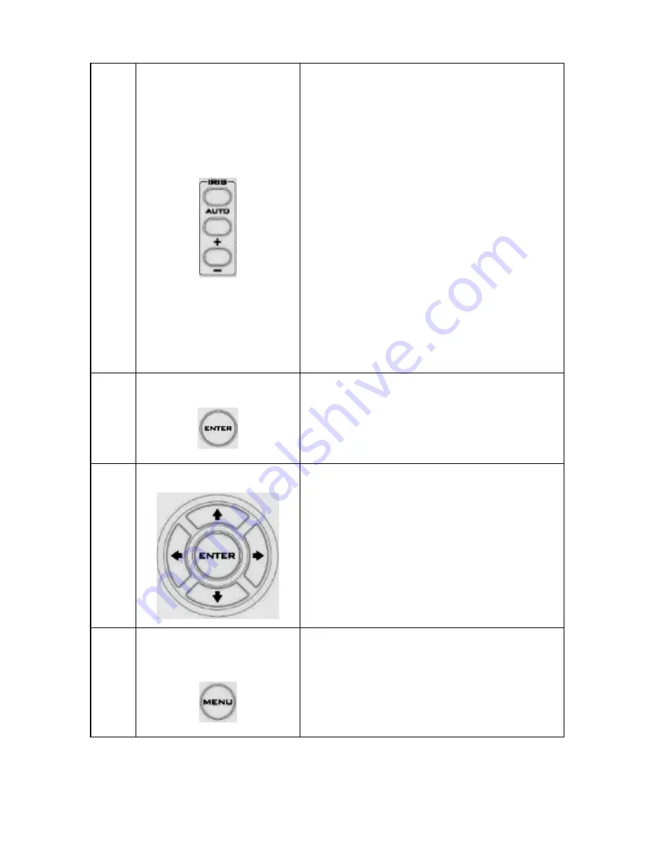
Auto Iris Control 


Make the subject appear brighter


Adjust the iris opening (aperture), to 

control the amount of light coming 

through the lens (i.e. the 

"exposure"). Press 

IRIS+

 button to 

enlarge the iris opening to allow 

more light to come in so that the 

subject appears brighter and press 

IRIS-

 button to shrink the iris 

opening to allow less light to come 

in so that the subject appears less 

bright. 


Press 

AUTO

 button activate auto Iris 

Control and press again to exit.  

10 

ENTER 


ENTER 

Press 

ENTER

 key to select a 

particular menu option or confirm a 

parameter value.  

11 

Direction Arrows 


Browse Menu Options 

Press 

UP

DOWN

LEFT

 and 

RIGHT


arrow buttons to browse the menu 

options or adjust parameter values.  

12 

Enter/ Exit Camera 

Menu 


Press the 

MENU

 button to Enter or 

Exit the Camera OSD Menu 

Summary of Contents for BC 80

Page 1: ...1 ...

Page 2: ... WARRANTY 5 STANDARD WARRANTY 5 TWO YEAR WARRANTY 5 DISPOSAL 6 1 INTRODUCTION 7 FEATURES 7 2 SYSTEM DIAGRAM 8 3 CONNECTIONS 9 FRONT VIEW 9 REAR PANEL 10 4 IR REMOTE CONTROL 13 5 OSD MENU OPTIONS 18 6 DIP SWITCH SETTINGS 28 7 RS 422 CONTROL PROTOCOL 29 7 1 PIN DESCRIPTIONS 29 ...

Page 3: ... Datavideo Technologies will try to give correct complete and suitable information However Datavideo Technologies cannot exclude that some information in this manual from time to time may not be correct or may be incomplete This manual may contain typing errors omissions or incorrect information Datavideo Technologies always recommend that you double check the information in this document for accu...

Page 4: ...s the ventilation openings on the bottom of the cabinet will be blocked This unit should never be placed near or over a heat register or radiator This unit should not be placed in a built in installation unless proper ventilation is provided 7 This product should only be operated from the type of power source indicated on the marking label of the AC adapter If you are not sure of the type of power...

Page 5: ...hnician to restore the unit to normal operation e When the product has been dropped or the cabinet has been damaged f When the product exhibits a distinct change in performance indicating a need for service Warranty Standard Warranty Datavideo equipment is guaranteed against any manufacturing defects for one year from the date of purchase The original purchase invoice or other documentary evidence...

Page 6: ...te equipment by handing it over to a designated collection point for the recycling of waste electrical and electronic equipment The separate collection and recycling of your waste equipment at the time of disposal will help to conserve natural resources and ensure that it is recycled in a manner that protects human health and the environment For more information about where you can drop off your w...

Page 7: ...control protocol supports SONY VISCA so that the camera can be controlled via RS 422 or DVIP interface Features HD Resolution 1 2 8 High Definition 2 0 M Pixels progressive CMOS sensor 30x optical zoom High definition formats supported 1080 59 94p 1080 50p 1080 59 94i 1080 29 97p 1080 25p 1080 50i 720 59 94p 720 50p Digital Noise Reduction Function DNR to reduce the noise and enable clearer image ...

Page 8: ...8 2 System Diagram ...

Page 9: ...emote control Tally Light As the camera is booting the tally light stays solid green and turns solid red for about three seconds just before the boot is complete The tally light remains solid green after the camera finishes booting Lens Camera lens for capturing images ...

Page 10: ...10 Rear Panel ...

Page 11: ...RS 422 Control Protocol for details 12V DC Power IN DC in socket connects the supplied 12V PSU The connection can be secured by screwing the outer fastening ring of the DC In plug to the socket Power Switch Turns ON OFF the camera Power LED Indicator Green Power ON OFF Power OFF DVIP Control Port Remote control port using the DVIP control protocol See DVIP Control Operation Guide for details ...

Page 12: ...grade For details please refer to the Firmware Upgrade section DIP Switch DIP Switch sets the camera VISCA ID Remote Control Protocol and Resolution Video Mode Selection Method and Camera ID Assignment For details please refer to the DIP Switch Settings section ...

Page 13: ...13 4 IR Remote Control Use the IR remote control that comes with the product package to operate the BC 80 Block Camera The IR remote control functions are described in the table below ...

Page 14: ...ronment Press Camera Select buttons to select a camera from Camera 1 to Camera 4 in a multi camera environment However before using the Camera Select function first assign an ID number CAM 1 CAM 4 to the camera intended for remote control operation by adjusting the DIP switch located at the rear of the camera Please refer to DIP Switch Settings section for details 4 Preset Setting Not Applicable ...

Page 15: ...pressing the AUTO FOCUS button 6 Auto Focus Control Automatically focus camera lens on a subject Press AUTO FOCUS button and camera lens will be automatically focused on the subject 7 Gain Control Adjust Brightness Press GAIN button to increase the brightness or GAIN button to decrease the brightness Press AUTO button to activate auto Gain Control and press again to exit 8 P T Speed Adjust Pan Til...

Page 16: ... button to shrink the iris opening to allow less light to come in so that the subject appears less bright Press AUTO button activate auto Iris Control and press again to exit 10 ENTER ENTER Press ENTER key to select a particular menu option or confirm a parameter value 11 Direction Arrows Browse Menu Options Press UP DOWN LEFT and RIGHT arrow buttons to browse the menu options or adjust parameter ...

Page 17: ...o the camera or W WIDE button to zoom out from the subject such that it appears to be far away from the camera 14 Zoom Speed Buttons 4 speed selection Adjust Zoom In Out Speed Press the ZOOM SPEED buttons to switch to different zoom speeds 4 being the highest and 1 being the lowest 15 Power Button Switch ON OFF camera ...

Page 18: ... control the amount of light coming through the lens The more the iris is opened the more light it lets in and the brighter the scene will be AGC The setting that automatically adjusts the amplification of the signal from the camera sensor DNR Digital Noise Reduction digitally removes any noise found in each image resulting in a clearer image 2 Video Output Selection Way This option configures how...

Page 19: ...sing the aperture setting so that the foreground and background of your images appear sharp Vivid Effect Vivid effect adjusts the color saturation which is basically the intensity of color in an image Pedestal Effect The pedestal effect enables exposure compensation which will engage the iris or auto gain control depending on the shooting situation For best results we recommend setting the pedesta...

Page 20: ... Focus 4 Pattern 4 Set DVIP 4 Reset All 4 Focus 5 Iris 5 Escape 5 Set IR 5 Update Software 5 Iris 6 AGC 6 PTZ INFO output 6 Escape 6 AGC 7 Escape 7 Escape 7 Fog Correction 8 Aperture 9 Vivid Effect 10 Pedestal Effect 11 Backlight Correct 12 Day Night Mode 13 Shutter 14 Gamma Mode 15 WD Mode 16 Escape First Level Main Options Second Level Sub Options Third Level Parameters Fourth Level Parameters S...

Page 21: ...ART ATW OFF SMART1 2 3 MWB RED COMPONENT 0 128 255 MWB BLUE COMPONENT 0 128 255 ESCAPE 4 Focus FOCUS MODE AUTO MANUAL AF SENSITIVITY LOW NORMAL FOCUS SPEED 1 4 ESCAPE 5 Iris IRIS MODE AUTO IRIS MANUAL MANUAL IRIS LEVEL F1 6 F2 0 F2 4 F2 8 F3 4 F4 F4 8 F5 6 F6 8 F8 F9 6 F11 F14 CLOSE ESCAPE 6 AGC DAY COLOR AGC AGC MODE OFF ON ...

Page 22: ... dB ESCAPE DNR DNR AT AGC ON ON OFF DNR LEVEL 0 1 2 3 4 5 ESCAPE ESCAPE 7 Escape 2 Video Output 1 Selection Way BY MENU BY SWITCH 2 Video Mode 1080i60 1080i50 720p60 720p50 1080p30 1080p25 1080p60 1080p50 3 CV Mode 16 9 4 3 4 Pattern OFF COLOR BAR 5 Escape 3 Remote Control 1 PAN TILT Reverse OFF P T P T ...

Page 23: ...200 38400 57600 115200 ESCAPE 5 Set IR IR GROUP ID Configurable using rear DIP switch ONLY CAM1 4 ESCAPE 6 PTZ INFO Output ON OFF 7 Escape 4 System 1 Display P T Z OSD PAN OSD ON OFF TILT OSD ON OFF ZOOM OSD ON OFF ESCAPE DEBUG OSD DEBUG IR OSD ON OFF DEBUG CAM OSD ON OFF DEBUG RS 422 OSD ON OFF DEBUG DVIP OSD ON OFF DEBUG M_CTL OSD ON OFF DEBUG REG OSD ON OFF DEBUG FRAME NO ON OFF PWR ON CAM TEST...

Page 24: ... 6 2 7 1 8 0 9 0 0 0 9 1 8 2 7 3 6 4 5 5 4 TILT offset ADJ 6 3 5 4 4 5 3 6 2 7 1 8 0 9 0 0 0 9 1 8 2 7 3 6 4 5 5 4 6 3 ESCAPE 3 Tally Light RED GREEN GREEN RED OFF 4 Reset All YES NO 5 Update Software SW VERSION ESCAPE MB CPU V01 17i MB FPGA V017 MCTL CPU V00 42 UPDATE ALL YES NO ESCAPE ...

Page 25: ...3 White Balance MODE AWB AUTO AWC ONE PUSH MWB MANUAL 3200K INDOOR 6500K OUTDOOR 4200K FLUO SMART ATW Enabled in AWB AUTO mode OFF SMART1 3 MWB RED COMPONENT 0 128 255 MWB BLUE COMPONENT 0 128 255 ESCAPE 4 Focus FOCUS MODE AUTO MANUAL AF SENSITIVITY LOW NORMAL FOCUS SPEED 1 2 3 4 ESCAPE 5 Iris IRIS MODE AUTO MANUAL Manual IRIS LEVEL F1 6 F2 0 F2 4 F2 8 ...

Page 26: ...AGC DAY COLOR AGC AGC MODE ON OFF MANUAL GAIN 0dB GAIN LIMIT GAIN LIMIT 9 dB 12 dB 15 dB 18 dB 21 dB 24 dB 27 dB 30 dB 33 dB 36 dB 39 dB ESCAPE DNR DNR AT AGC ON ON OFF DNR LEVEL 0 1 2 3 4 5 ESCAPE 7 Fog Correction FOG CORRECTION OFF ON ESCAPE 8 Aperture 0 15 ...

Page 27: ... is enabled after AGC is turned on 12 Day Night Mode B W COLOR 13 Shutter SHUTTER SPEED NORMAL 1 100 1 125 1 250 1 500 1 1000 ESCAPE 14 Gamma Mode STANDARD MODE1 WD OFF MODE2 WD OFF MODE3 WD OFF MODE4 WD OFF 15 WD Mode ON OFF This option is enabled after AGC is turned on 16 Escape 6 Escape ...

Page 28: ...SW 5 6 7 Resolution OFF OFF OFF 1920x1080i60 ON OFF OFF 1920x1080i50 OFF ON OFF 1280x720p60 ON ON OFF 1280x720p50 OFF OFF ON 1920x1080p30 ON OFF ON 1920x1080p25 OFF ON ON 1920x1080p60 ON ON ON 1920x1080p50 DIP SW 8 Video Mode Selection Method ON ON video mode selectable by DIP switch only OFF OFF video mode selectable by menu DIP SW 9 10 Camera Select Function IR Remote Control Camera ID Assignmen...

Page 29: ...rown 8 NC 7 2 Control Operation Guide 7 2 1 Overview of VISCA In VISCA the side outputting commands for example a computer is called the controller while the side receiving the commands such as the BC 80 is called the peripheral device The BC 80 serves as a peripheral device in VISCA In VISCA up to seven peripheral devices like the BRC 300 P can be connected to one controller using communication c...

Page 30: ...eripheral device is set by sending address commands during the initialization of the network When the address of the controller is fixed at 1 through 7 The addresses of the peripheral devices will be set on a pre selected number Within a single system the same number can be used only once If an address switch number other than 0 is to be used change the BC 80 address switch to a different number b...

Page 31: ...ssigned address 2 is 82H In the command list as the header is 8X input the address of the BC 80 at X The header of the reply packet from the BC 80 assigned address 1 is 90H The packet from the BC 80 assigned address 2 is A0H Some of the commands for setting BC 80 units can be sent to all devices at one time broadcast In the case of broadcast the header should be hexadecimal 88H When the terminator...

Page 32: ... one time in a Vertical cycle it takes the maximum 1V cycle time for an ACK Completion to be returned If the Command ACK Completion communication time can be cut shorter than the 1V cycle time then every 1V cycle can receive a Command From this point if 2 or more commands in a row are to be sent wait ...

Page 33: ... camera 1 06 Pan Tilter X 1 to 7 BC 80 address Responses for commands and inquiries ACK message Returned by the BC 80 when it receives a command No ACK message is returned for inquiries Completion message Returned by the BC 80 when execution of commands or inquiries is completed In the case of inquiry commands it will contain reply data for the inquiry after the 3 rd byte of the packet If the ACK ...

Page 34: ...o the BC 80 it is normal to send the next command message after waiting for the completion message or error message to return As the completion message or error message also has a socket number it indicates which command has ended The ACK message is not returned for these commands and inquiries and only the completion message of socket number 0 is returned 7 2 3 VISCA Device Setting Command Before...

Page 35: ...ns ACK when a command has been accepted and Completion when a command has been executed 81 01 04 38 FF Example 90 60 02 FF Syntax Error Accepted a command which is not supported or a command lacking parameters 81 01 04 38 02 FF Example 90 60 03 FF Command Buffer Full There are two commands currently being executed and the command could not be accepted 81 01 04 08 02 FF Example 90 61 41 FF Command ...

Page 36: ...eterminate Do not transmit the command except Address Set IF_Clear CAM_POWER when menu panel shows on the screen In that case clear the menu panel first using CAM_Menu Command and then proceed 7 2 5 VISCA Camera Issued Messages ACK Completion Messages Command Command Message Comments ACK z0 4y FF y Socket No Returned when the command is accepted Completion z0 5y FF y Socket No Returned when the co...

Page 37: ...n an invalid socket number is specified Command Not Executable z0 6y 41 FF y Socket No Returned when a command cannot be executed due to current conditions For example when commands controlling the focus manually are received during auto focus 7 2 6 BC 80 Commands BC 80 Command List Command Set Command Command Packet Comments AddressSet Broadcast 88 30 01 FF Address Set IF_Clear Broadcast 88 01 00...

Page 38: ...1 04 08 00 FF Far Standard 8x 01 04 08 02 FF Near Standard 8x 01 04 08 03 FF Direct 8x 01 04 48 0p 0q 0r 0s FF pqrs Focus Position Auto Focus 8x 01 04 38 02 FF AF ON OFF Manual Focus 8x 01 04 38 03 FF One Push Trigger 8x 01 04 18 01 FF One Push AF Trigger CAM_WB Auto 8x 01 04 35 00 FF Normal Auto Indoor 8x 01 04 35 01 FF Indoor Mode Outdoor 8x 01 04 35 02 FF Outdoor Mode One Push WB 8x 01 04 35 03...

Page 39: ... 01 04 43 00 00 0p 0q FF R Gain Direct pq 00 to FF CAM_BGain Reset 8x 01 04 04 00 FF Default B Gain setting Up 8x 01 04 04 02 FF Down 8x 01 04 04 03 FF Direct 8x 01 04 44 00 00 0p 0q FF B Gain Direct pq 00 to FF CAM_AE Full Auto 8x 01 04 39 00 FF Automatic exposure mode Manual 8x 01 04 39 03 FF Manual control mode Shutter Priority 8x 01 04 39 0A FF Shutter priority automatic exposure mode ...

Page 40: ... 04 0A 02 FF Down 8x 01 04 0A 03 FF CAM_Iris Reset 8x 01 04 0B 00 FF Default Iris Setting Up 8x 01 04 0B 02 FF Down 8x 01 04 0B 03 FF Direct 8x 01 04 4B 00 00 0p 0q FF pq Iris Position CAM_Gain Reset 8x 01 04 0C 00 FF Default Gain setting Up 8x 01 04 0C 02 FF Down 8x 01 04 0C 03 FF Direct 8x 01 04 4C 00 00 0p 0q FF pq Iris Position CAM_Backlight On 8x 01 04 33 02 FF Back Light ON OFF ...

Page 41: ...p 0 to 50 CAM_Menu On 8x 01 06 06 02 FF Menu ON Off 8x 01 06 06 03 FF Menu OFF Pan tilt Drive Up 8x 01 06 01 VV WW 03 01 FF PanSpeed VV 01 Slow to 18h Fast TiltSpeed WW 01 Slow to 18h Fast Down 8x 01 06 01 VV WW 03 02 FF Left 8x 01 06 01 VV WW 01 03 FF Right 8x 01 06 01 VV WW 02 03 FF UpLeft 8x 01 06 01 VV WW 01 01 FF UpRight 8x 01 06 01 VV WW 02 01 FF DownLeft 8x 01 06 01 VV WW ...

Page 42: ...peed VV 01 Slow to 18h Fast YYYYY Pan Position ZZZZ Tilt Position RelativePosition 8x 01 06 03 VV 00 0Y 0Y 0Y 0Y 0Y 0Z 0Z 0Z 0Z FF Speed VV 01 Slow to 18h Fast YYYYY Pan Position ZZZZ Tilt Position Home 8x 01 06 04 FF Reset 8x 01 06 05 FF CAM_ImgFlip On 8x 01 04 66 02 FF Off 8x 01 04 66 03 FF Cam_PanReverse On 8x 01 7E 01 06 00 01 FF Off 8x 01 7E ...

Page 43: ...et PT Speed 8x 01 7E 01 0B 0p 0q FF p Memory number 0 to 50 q Speed 1 to 18 fast See the section under VISCA Command Setting Values BC 80 Inquiry Command List Inquiry Command Command Packet Inquiry Packet Comments CAM_PowerInq 8x 09 04 00 FF y0 50 02 FF On y0 50 03 FF Off Standby CAM_ZoomPosInq 8x 09 04 47 FF y0 50 0p 0q 0r 0s FF pqrs Zoom Position CAM_FocusModeI nq 8x 09 04 38 FF y0 50 02 FF Auto...

Page 44: ...WB y0 50 05 FF Manual CAM_RGainInq 8x 09 04 43 FF y0 50 00 00 0p 0q FF pq R Gain CAM_BGainInq 8x 09 04 44 FF y0 50 00 00 0p 0q FF pq B Gain CAM_AEModeInq 8x 09 04 39 FF y0 50 00 FF Full Auto y0 50 03 FF Manual y0 50 0A FF Shutter Priority y0 50 0B FF Iris Priority CAM_ShutterPosI nq 8x 09 04 4A FF y0 50 00 00 0p 0q FF pq Shutter Position CAM_IrisPosInq 8x 09 04 4B FF y0 50 00 00 0p 0q FF pq Iris P...

Page 45: ...ry number for PTZ last operated CAM_MENUInq 8x 09 06 06 FF y0 50 02 FF On y0 50 03 FF Off CAM_VersionInq 8x 09 00 02 FF y0 50 00 01 mn pq rs tu vw FF mnpq Model Code 04xx rstu ROM version vw Socket Number 02 CAM_ImgFlipInq 8x 09 04 66 FF y0 50 02 FF On y0 50 03 FF Off CAM_PanReverseI nq 8x 09 7E 01 06 FF y0 50 01 FF On y0 50 00 FF Off CAM_TiltReverseI nq 8x 09 7E 01 09 FF y0 50 01 FF On ...

Page 46: ...pq Pan Max Speed rs Tilt Max Speed PanTilt_Position 8x 09 06 12 FF y0 50 0p 0q 0r 0s 0t 0u 0v 0w 0x FF pqrst Pan Position uvwx Tilt Position Tally 8x 09 7E 01 0A FF y0 50 02 FF On y0 50 03 FF Off PanTilt_Memory_ Speed 8x 09 7E 01 0B 0p FF y0 50 0q FF p Preset No 0 50 qq Speed 1 18 h See the section under VISCA Command Setting Values ...

Page 47: ... DHCP mode User is allowed to re configure to static IP address TCP IP Control port numbers TCP port 5002 UDP port 5002 8 3 Packet Data Control Command Packet TCP Byte 8 bits Descriptions 0 Packet Length High Byte 1 Packet Length Low Byte 2 Command_Data 0 513 Command_Data 511 Broadcast Packet Byte 8 bits Descriptions 0 Packet Length High Byte 1 Packet Length Low Byte 2 0x80 3 Command 4 Parameter 1...

Page 48: ...er 2 0x54 Parameter 3 0x48 Parameter 4 0x5F Parameter 5 0x52 Parameter 6 0x45 Parameter 7 0x51 Command Return from DVIP device Length Descriptions 1 Byte Data Length High Byte 1 Byte Data Length Low Byte 1 Byte 0x80 1 Byte 0x00 1 Byte DHCP 0 Disable 1 Enable 16 Bytes DHCP Host name 15 bytes max Null 0x00 terminated 6 Bytes MAC Address 4 Bytes IP Address 4 Bytes Netmask 4 Bytes Gateway 4 Bytes Prim...

Page 49: ...P MAC address 3 Parameter 5 DVIP MAC address 4 Parameter 6 DVIP MAC address 5 Parameter 7 0x46 Parameter 8 0x57 Parameter 9 0x56 Parameter 10 0x45 Parameter 11 0x52 Parameter 12 0x5F Parameter 13 0x52 Parameter 14 0x45 Parameter 15 0x51 Command Return from DVIP device Length Descriptions 1 Byte 0x00 Data Length High Byte 1 Byte 0x06 Data Length Low Byte 1 Byte 0x80 1 Byte 0x01 1 Byte Firmware Revi...

Page 50: ...Parameter 6 DVIP MAC address 5 Parameter 7 0x53 Parameter 8 0x45 Parameter 9 0x54 Parameter 10 0x5F Parameter 11 0x44 Parameter 12 0x48 Parameter 13 0x43 Parameter 14 0x50 Parameter 15 0x4D Parameter 16 0x4F Parameter 17 0x44 Parameter 18 0x45 Parameter 19 0x00 Disable 0x01 Enable Command Return from DVIP device Length Descriptions 1 Byte 0x00 Data Length High Byte 1 Byte 0x06 Data Length Low Byte...

Page 51: ...ter 7 0x53 Parameter 8 0x45 Parameter 9 0x54 Parameter 10 0x5F Parameter 11 0x49 Parameter 12 0x50 Parameter 13 0x41 Parameter 14 0x44 Parameter 15 0x52 Parameter 16 IP_Address 0 Parameter 17 IP_Address 1 Parameter 18 IP_Address 2 Parameter 19 IP_Address 3 Parameter 20 Gateway 0 Parameter 21 Gateway 1 Parameter 22 Gateway 2 Parameter 23 Gateway 3 Command Return from DVIP device Length Descriptions...

Page 52: ... DVIP MAC address 5 Parameter 7 0x52 Parameter 8 0x45 Parameter 9 0x53 Parameter 10 0x45 Parameter 11 0x54 Command Return from DVIP device Length Descriptions 1 Byte 0x00 Data Length High Byte 1 Byte 0x06 Data Length Low Byte 1 Byte 0x80 1 Byte 0x04 1 Byte 0x06 ACK or 0x15 NACK Broadcast Command List Get Device Model Number Command Issue to DVIP device Get Device Model Number Command 0x05 Paramete...

Page 53: ...ameter 17 0x4E Parameter 18 0x41 Parameter 19 0x4D Parameter 20 0x45 Command Return from DVIP device Length Descriptions 1 Byte 0x00 Data Length High Byte 1 Byte 0x06 Data Length Low Byte 1 Byte 0x80 1 Byte 0x04 16 Bytes Device Model Number is 16 Bytes maximum use null padding 0x00 if it is less than 16 bytes UDP Packet Byte 8 bits Descriptions 0 Packet Length High Byte 1 Packet Length Low Byte 2 ...

Page 54: ...6 0x45 Parameter 7 0x51 Command Return from DVIP device Length Descriptions 1 Byte Data Length High Byte 1 Byte Data Length Low Byte 1 Byte 0x80 1 Byte 0x00 1 Byte DHCP 0 Disable 1 Enable 16 Bytes DHCP Host name 15 bytes max Null 0x00 terminated 6 Bytes MAC Address 4 Bytes IP Address 4 Bytes Netmask 4 Bytes Gateway 4 Bytes Primary DNS address 4 Bytes Secondary DNS address UDP Command List Request ...

Page 55: ... Length High Byte 1 Byte 0x06 Data Length Low Byte 1 Byte 0x80 1 Byte 0x01 1 Byte Firmware Revision Major Number 1 Byte Firmware Revision Minor Number UDP Command List Set DHCP Mode Command Issue to DVIP device Set DHCP Mode Command 0x02 Parameter 1 0x53 Parameter 2 0x45 Parameter 3 0x54 Parameter 4 0x5F Parameter 5 0x44 Parameter 6 0x48 Parameter 7 0x43 Parameter 8 0x50 Parameter 9 0x4D Parameter...

Page 56: ...d List Set IP Address Gateway Address Command Issue to DVIP device Set IP Address Command 0x03 Parameter 1 0x53 Parameter 2 0x45 Parameter 3 0x54 Parameter 4 0x5F Parameter 5 0x49 Parameter 6 0x50 Parameter 7 0x41 Parameter 8 0x44 Parameter 9 0x52 Parameter 10 IP_Address 0 Parameter 11 IP_Address 1 Parameter 12 IP_Address 2 Parameter 13 IP_Address 3 Parameter 14 Gateway 0 Parameter 15 Gateway 1 Pa...

Page 57: ...to Factory Default Command 0x04 Parameter 1 0x52 Parameter 2 0x45 Parameter 3 0x53 Parameter 4 0x45 Parameter 5 0x54 Command Return from DVIP device Length Descriptions 1 Byte 0x00 Data Length High Byte 1 Byte 0x06 Data Length Low Byte 1 Byte 0x81 1 Byte 0x04 1 Byte 0x06 ACK or 0x15 NACK UDP Command List Set DHCP Host Name Command Issue to DVIP device Set DHCP Host Name Command 0x09 Parameter 1 0x...

Page 58: ... Return from DVIP device Length Descriptions 1 Byte 0x00 Data Length High Byte 1 Byte 0x05 Data Length Low Byte 1 Byte 0x81 1 Byte 0x09 1 Byte 0x06 ACK or 0x15 NACK UDP Command List Set Netmask Command Issue to DVIP device Set Netmask Command 0x0B Parameter 1 0x53 Parameter 2 0x45 Parameter 3 0x54 Parameter 4 0x5F Parameter 5 0x4E Parameter 6 0x45 Parameter 7 0x54 Parameter 8 0x4D Parameter 9 0x41...

Page 59: ...te 1 Byte 0x81 1 Byte 0x0B 1 Byte 0x06 ACK or 0x15 NACK UDP Command List Set Gateway Address Command Issue to DVIP device Set Gateway Address Command 0x0C Parameter 1 0x53 Parameter 2 0x45 Parameter 3 0x54 Parameter 4 0x5F Parameter 5 0x47 Parameter 6 0x41 Parameter 7 0x54 Parameter 8 0x45 Parameter 9 0x57 Parameter 10 0x41 Parameter 11 0x59 Parameter 12 Gateway 0 Parameter 13 Gateway 1 Parameter ...

Page 60: ...and 0x0D Parameter 1 0x53 Parameter 2 0x45 Parameter 3 0x54 Parameter 4 0x5F Parameter 5 0x50 Parameter 6 0x52 Parameter 7 0x49 Parameter 8 0x44 Parameter 9 0x4E Parameter 10 0x53 Parameter 11 Primary_DNS_IP 0 Parameter 12 Primary_DNS_IP 1 Parameter 13 Primary_DNS_IP 2 Parameter 14 Primary_DNS_IP 3 Command Return from DVIP device Length Descriptions 1 Byte 0x00 Data Length High Byte 1 Byte 0x05 Da...

Page 61: ...rameter 10 0x53 Parameter 11 Secondary_DNS_IP 0 Parameter 12 Secondary _DNS_IP 1 Parameter 13 Secondary _DNS_IP 2 Parameter 14 Secondary _DNS_IP 3 Command Return from DVIP device Length Descriptions 1 Byte 0x00 Data Length High Byte 1 Byte 0x05 Data Length Low Byte 1 Byte 0x81 1 Byte 0x0E 1 Byte 0x06 ACK or 0x15 NACK UDP Command List Initial DVIP Configuration Command Issue to DVIP device Initial ...

Page 62: ... Parameter N Null 0x00 Parameter N 1 MAC_Address 0 3 Parameter N 5 IP_Address 0 3 Parameter N 9 Gateway_IP 0 3 Parameter N 13 Net_Mask 0 3 Parameter N 17 Primary_DNS_IP 0 3 Parameter N 21 Secondary_DNS_IP 0 3 Command Return from DVIP device Length Descriptions 1 Byte 0x00 Data Length High Byte 1 Byte 0x05 Data Length Low Byte 1 Byte 0x81 1 Byte 0x0F 1 Byte 0x06 ACK or 0x15 NACK ...

Page 63: ...e MENU button 3 Browse to 4 SYSYEM 4 UPDATE SOFTWARE 4 UPDATE ALL YES ENTER 4 Wait for another five minutes until the following lines appear on the screen Updated FPGA OK Updated MCPU OK The OSD will flash Write OK Power ON Again Note it takes approximately 5 7 minutes to complete the update 5 Turn off the device by unplugging the power cord Plug the power cord back into the socket and then turn o...

Page 64: ...64 10 Dimensions All measurements in millimeters mm ...

Page 65: ...00 sec Gamma Control Off Normal Standard Mode 1 4 Iris Control Auto Manual Digital Noise Reductions 0 5 On Screen Display OSD English White Balance AWB MWB One push WB Outdoor Indoor Fluorescent AGC Gain Control Auto Manual 0 to 28 step Max Gain Limit 6 to 28 step Zoom Ratio 30x Optical Zoom Mirror OFF Horizontal Vertical H V Color Bar On Off Full Bar Focus Mode Auto Manual Day Night IR Auto Color...

Page 66: ... SDI x 1 Control Protocol VISCA DVIP Protocol Remote Control RS 422 DVIP by RJ 45 interface F W Update USB 2 0 IR Control One IR controller Others Operating Temperature 0 C 50 C Storage Temperature 10 C 60 C Operating Humidity 10 to 80 non condensing ...

Page 67: ...67 Service and Support ...

Reviews: