background image

44

Getting Started with DT800 

dataTaker

UM-0071-A0

trends to as many as six Y axes (linear or logarithmic). 
You can also open additional chart windows if 
necessary. (To add a chart window, choose 

New

 on 

the File menu, then click the 

Chart

 button.)

You can watch the trends update as the real-time or 
replay data arrives, or you can home-in on a section of 
the data already charted (while incoming data 
continues to be recorded by the window).

Time (vertical) and data (horizontal) rulers allow you to 
read precise coordinates from the trends (Figure 47).

Mouse Power

In a DeLogger chart window, you use the mouse to 
select and scale sections of the trend graphs for 
optimal viewing of regions you’re interested in. Figures 
45 and 46 show how you do this.

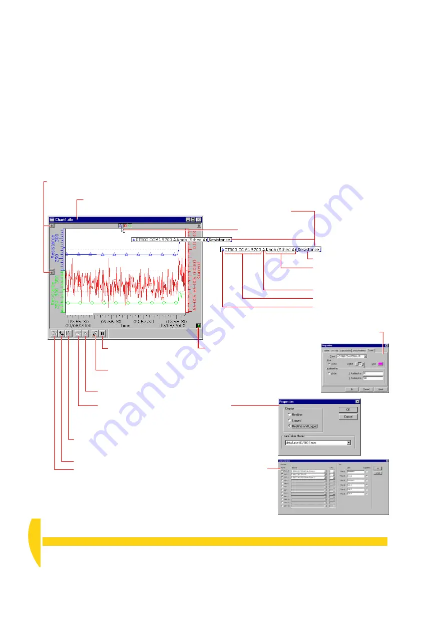
An information bar

appears when you rest

the mouse over a graph’s 

Show/hide

 button. 

Play Chart 

button (and indicator). 

The chart moves (like the paper in a 

chart recorder) and new data enters 

the right-hand side of the trend area 

when when this button is pressed (lit).

Relocate a graph and its scale 

by dragging its 

scale handle

.

Connection

Channel 

label

 (from the 

channel’s Label column in 

the program builder)

Schedule

 (A, B, C,…K)

The graph’s 

data point 

symbol

 (if you’ve applied 

one — double-click in the 

trend area and go to the 

Curves tab in the dialog 

box that opens)

Axis label

Select channels

 to be plotted in this chart window (the Chart Channels 

dialog box opens). Only available when the window is in Edit Mode.

Click the 

Auto Re-scale

 button to fit the trend graphs into the chart 

window with maximum horizontal and vertical resolution (squeezes 

all the data into the window).

Rotate

 the graphs so that they move from top to bottom.

Open the chart window’s 

Properties

 dialog box

(to control the display of realtime and/or logged data). 

Only available when the window is in Edit Mode.

Clear

 the chart window. Only available 

when the window is in Edit Mode.

Pause

 the return of data. 

Only available when the 

window is in Run Mode.
Turn 

Edit Mode

 on/off.

“Edit” appears after the window name in the 

title bar when the window is in Edit Mode.

F

IGURE 

44

More features of the DeLogger chart window

Summary of Contents for DT800

Page 1: ...UM 0071 A0 ...

Page 2: ...UM 0071 A0 ...

Page 3: ...a registered trademark of dataTaker Pty Ltd All other brand and product names are trademarks or registered trademarks of their respective holders Copyright 2000 dataTaker Pty Ltd Getting Started with DT800 dataTaker UM 0071 A0 ...

Page 4: ...hurry you can go directly to the DT800 dataTaker User s Manual supplied with your DT800 Extras All readers will benefit from the Extras included with many of the topics Extras are additional information intended to supplement each topic You don t need to read the Extras to be able to work through this guide although we do recommend you read them at some time because they contain valuable backgroun...

Page 5: ...R 6 SEE YOUR DATA FORM WINDOW 6 1 DeLogger s Form Window 38 6 2 View the Returned Data 41 6 3 Set the DT800 s Date and Time 42 CHAPTER 7 SEE YOUR DATA CHART WINDOW 7 1 DeLogger s Chart Window 43 7 2 Chart the Returned Data 48 CHAPTER 8 SEE YOUR DATA MIMIC WINDOW 8 1 DeLogger s Mimic Window 49 8 2 Display Returned Data in a Meter 50 8 3 Replay a File to a Meter 51 8 4 Add a Graphic 52 8 5 Disconnec...

Page 6: ...simply making a permanent record of data that has been collected printing or plotting it writing it on a sheet of paper or storing it on a computer s hard disk or in electronic memory Others perceive data logging as the total operation of collecting data and making a permanent record of it Therefore they see data acquisition as part of data logging Now with dataTaker any distinction between these ...

Page 7: ...culations on the measurements average standard deviation maximum minimum log the converted measurements and the results of calculations to its internal memory and or a removable memory card or transfer them to a computer display all of this on a computer screen return data directly to a computer in real time that is as each measurement is made as well as or instead of logging it raise alarms when ...

Page 8: ...mpensation terms which are beyond the scope of this guide Just be aware that raw measurements usually have to be converted before they become the meaningful quantities that are useful to you Figure 3 One of the features of the DT800 is that it automatically performs these conversions for you All you have to do is tell the logger what type the sensor is a type T thermocouple for example and the mic...

Page 9: ...ode the DT800 returns data in a predictable repeatable comprehensive format ready to be imported into spreadsheets and other data analysis software Real time data can be returned in either free or fixed format mode but logged data is always returned in fixed format mode These two modes are discussed in Format of Returned Data in Part A of the DT800 dataTaker User s Manual Data Display You can conn...

Page 10: ...ipping in Part C of the DT800 dataTaker User s Manual supplied with your DT800 Good Power Practice The recommended method of working with the DT800 is while you are programming it back at base to power it from the mains using a mains adaptor The mains adaptor supplies the logger and charges the main internal battery When you ve finished programming and are ready to use the logger in the field you ...

Page 11: ...s section introduces you to some data acquisition and logging terms you ll need right away Others are explained as they arise Sensors and Transducers Origins of data in a data acquisition and logging system Sensors are the raw basic devices that detect variable quantities temperature pressure flow and convert them into electrical signals Sensors see hear taste sniff or feel the environment and tel...

Page 12: ...e same in form and function as the serial port on your PC This means that you can connect a modem or other serial device to the DT800 using standard serial cables intended for connecting the modem to a computer NOTE The comms cable supplied with your DT800 is not the same as that supplied with dataTaker DT50 and DT500 600 Series data loggers Serial Channel The DT800 has a serial port for smart sen...

Page 13: ...sensor wiring a potentiometer variable resistance mounted in a child s building block a thermocouple a DT800 CD contains software and manuals a DT800 dataTaker User s Manual the document you re reading now Getting Started with DT800 dataTaker If anything is missing contact your supplier immediately b You also need a PC running Windows 95 98 2000 or NT with a CD ROM drive a 200MHz Pentium II proces...

Page 14: ...pplied with your DT800 2 3 MAKE THE HARDWARE CONNECTION For the computer to talk to the DT800 and the DT800 to return data to the computer you must establish a communications link between the two You can use any of the links described in the Extras panel Communications Links but in this guide we ll use the simplest of all the comms cable supplied with the DT800 You ll connect it between the DT800 ...

Page 15: ...ur DT800 It s the child s building block with a knob on top and four wires b Connect the potentiometer s yellow and white wires to the and terminals of analog channel 1 on the front panel of the DT800 as shown in Figure 9 To open the terminals we recommend that you use one of the cage clamp tools supplied refer to Connecting Sensors to Channel Terminals in Part B of the DT800 dataTaker User s Manu...

Page 16: ...nicate with your logger you ll find that DT800 friendly software packages incorporate productivity features specific to data acquisition data logging and the DT800 that make it pointless to use anything else DeLogger used predominately throughout this guide has a totally graphical interface which means that knowledge of the dataTaker programming language is not required Instead you supervise the D...

Page 17: ...1am and 3pm every Friday SiteAdmin a utility that allows you to clear DeLogger s error and alarm logs Uninstall DeLogger use to remove DeLogger from the hard disk Re Installing and Project Compatibility Earlier Versions If an earlier version that is pre version 4 of DeLogger already exists on the computer you can do one of the following Clean Install Remove the existing version use Windows Add Rem...

Page 18: ...600 series dataTakers and Prog1 dl8 is for your DT800 f Click Prog1 dlp s minimize button in its title bar You re not using the DT500 600 program builder in this tutorial Enabling DeLogger Pro If you purchase DeLogger Pro or purchase an upgrade from DeLogger to DeLogger Pro you ll receive a serial number that you use as follows If you ve purchased DeLogger Pro Install and start DeLogger exactly as...

Page 19: ...his Connection specifies that the DT800 is directly connected to the computer s COM1 serial port So if you chose to plug the comms cable into a serial port other than COM1 on the back of your computer modify the dt800 Com1 Connection in DeLogger now Connections menu Properties Connection Troubleshooting If DeLogger responds with an Error connecting to message try the following Check that the comms...

Page 20: ...g in the DT800 how much data storage memory is used and free in the DT800 and so on you can send this command simply to confirm that you re connected to the DT800 b Look through the Status dialog box tabs to familiarize yourself with the information you can get from it then click OK Flow Control Flow control is a communications feature that allows communicating devices to control each other s tran...

Page 21: ...CHAPTER 3 SET UP THE DELOGGER SOFTWARE Verify the Connection 21 UM 0071 A0 FIGURE 15 The five tabs of DeLogger s DT800 Status dialog box ...

Page 22: ... which you ll use in later chapters Be sure not to miss More Important Concepts and Terminology on page 28 4 1 THE BIG PICTURES Figure 16 is an overview of the window types available in a DeLogger project and some of the things you can do with them Figure 17 shows the relationship between DeLogger projects programs schedules and channels Figure 18 shows how DeLogger starts up the first time after ...

Page 23: ...heet window load a replay file one row per timestamp one column per channel Then manipulate the data save it in a variety of formats or export it directly into Microsoft Excel Dynamic data views these DeLogger windows display incoming real time or replay data live Note You can open more than one of each of these window types in any DeLogger project choose New from the File menu Load text file cmd ...

Page 24: ...ls Other commands Comments Program Builder 2 Program 2 Schedule Channel details Schedule Channel details Other commands Comments Program Builder Program Schedule Channel details Other commands Comments DeLogger s conceptual hierarchy project program job schedule channel PROJECT B Program Builder Program Schedule Channel details Channel details Schedule Channel details Other commands Comments Progr...

Page 25: ...over a button or a menu item Use the View menu to show or hide the status bar The document bar gives you quick access to DeLogger s windows Single clicking a window s name in the document bar brings that window to the front in its current view state minimized maximized or in between It s like choosing a window using the Window menu only faster Double clicking a window s name in the document bar br...

Page 26: ...00 the Connection dialog box opens Open a full page Print Preview of the current window Save the current project Open another project Send the STATUS command to the DT800 Send the TEST command to the DT800 Halt the current schedule in the DT800 Run Go the current schedule in the DT800 Start the Unload process the first Unload dialog box opens Quit stop the unload process Open the Memory Card Optio...

Page 27: ...OGGER DeLogger s Menus 27 UM 0071 A0 4 3 DELOGGER S MENUS 1 1 2 2 3 3 4 4 5 5 6 6 7 7 7 7 7 7 7 8 8 9 9 10 10 11 11 7 Menu changes according to which DeLogger window is front most Menu bar FIGURE 20 DeLogger s menus sub menus not shown ...

Page 28: ...t the appropriate Connection name from DeLogger s live Connect dialog box or Replay dialog box and click OK Figure 22 Data Site A source of data DeLogger data sites can be external a DT800 or to be more precise the Connection to a DT800 internal a replay file or to be more precise the Connection to a replay file DeLogger display and capture engine DeLogger Replay file internal data site Ethernet n...

Page 29: ...800 the terms program and job mean the same thing Because the DT800 works with program entities called jobs every program you create in DeLogger is automatically tagged as a job when you send it to a DT800 This tagging is almost invisible to the user you can see it if you Load DLP Program Text into a text window entry screen It s necessary for the DT800 to recognise a DeLogger program but not for ...

Page 30: ...format that DeLogger can replay to its form chart text and mimic windows just as if the data was arriving in real time except that you can control the speed of the replay see Figure 25 You can save both real time data and logged data unloaded from a DT800 as a replay file DeLogger can also replay existing dx8 and dxu files dataTaker unload files A replay file is just another data site to link to i...

Page 31: ...down lists and dialog boxes Important Program Builder Facts Each program builder window creates just ONE DT800 program Although the program may contain several schedules and involve many DT800 channels there is only one program per program builder A project can contain more than one program builder that is more than one program Figure 17 on page 24 illustrates this To add another project builder w...

Page 32: ...ings at different times or according to different triggers Select a schedule here Immediate a once only scan or triggered A B C K Fixed columns Scrollable columns A program builder s program consists of everything specified on all of these tabs scroll right to reveal more tabs FIGURE 26 DeLogger s DT800 program builder general sequence of use Click this Configure button to open the Rate dialog box...

Page 33: ...alog box is open notice the other options available Name Schedules can have optional names for identification for example Boiler1 and HOURLY spaces are not allowed If no name is given schedule identification defaults to RA for schedule A RB for schedule B and so on Trigger on Events Open the Event s drop down list to see the event types you can use to trigger a schedule Trigger While Open the Whil...

Page 34: ...torial but you can read more about them in Other Schedules and Scans in Part D of the DT800 dataTaker User s Manual f In the Options row of the program builder leave Logging and Go ticked Then when you send the program you re currently building to the DT800 these options instruct the DT800 to run Go schedule A and to log its data Single click the Burst field to see Burst information here FIGURE 28...

Page 35: ...hedule because tab A at the bottom of the program builder window is the only one in which you ve assigned a channel In later chapters you ll add another channel to schedule A another schedule schedule B to the program Single click in the Signal column of R1 the first row of the Channel Definitions area Click the drop down list button that appears in the Signal column of R1 Click Resistance in the ...

Page 36: ...u did this in Make the Software Connection back on page 19 all is now ready for you to send your program Send your program to the DT800 To do this a Make sure that Prog1 dl8 is the front most window single click it if you re not sure Always take care if you have more than one DT800 project builder in any project DeLogger sends only the program of the active program builder so make sure the correct...

Page 37: ...e tabs the DT800 configuration settings on the Switches Parameters and Global tabs Event Logs The Event Logs window Figure 34 displays messages on the Message tab errors on the Errors tab alarms on the Alarms tab If you tick Show Alarm Events on the View menu DeLogger opens this window every time an alarm occurs If you tick Show Error Events on the View menu DeLogger opens this window every time a...

Page 38: ...ete worksheets at any time explained in the lower right hand corner of Figure 35 Select a worksheet by clicking its tab Drag the splitter bar to shrink or enlarge the tab space Double right click anywhere in a worksheet to open it in the Formula One Workbook Designer where additional commands are available if you need them for example Sheet Insert Sheet Sheet Delete Sheet Data Recalc Rename a work...

Page 39: ... next scan Scale view down zoom out Scale view up zoom in Show hide gridlines Show hide row and column headers Turn Edit Mode on off Open the form window s Properties dialog box to control the display of realtime and or logged data Edit appears in the title bar when the window is in Edit Mode To replace the row number with a custom name double click the row number the Header Name dialog box opens ...

Page 40: ...ger s menu bar is Form see Figure 20 on page 27 Commands on this menu are specific to the form window and some are duplicated by buttons on the form toolbar Figure 38 Send the X schedule command polled or scan on host request schedule Pause the return of data Reset all values in the Low Value column to zero updated at the next scan Reset all values in the High Value column to zero updated at the n...

Page 41: ...ce channel type this is the default channel ID it is replaced by any channel label you create in the program builder you ll do this in Add a Channel Label on page 55 e In the Select Channel for Row 1 dialog box highlight one click your channel name and click OK See also the Clearing the Form Window Extras panel page 42 f Turn Edit Mode off un tick Edit Mode on the form menu or click release the Ed...

Page 42: ...d sends it your computer s date and time a progress dialog box appears momentarily c Observe the Date column again The DT800 is now returning the correct date and time Clearing the Form Window To clear one or more rows in the form window highlight the row s Shift click and Ctrl click work for multiple rows then press Delete on your keyboard A dialog box opens in which you select what you want to c...

Page 43: ...ve separate trend graphs per chart window and you can assign the Chart toolbar The buttons duplicate commands found on the Chart menu See Drag it from its docked position to create a floating toolbar Drag a scale s handle to relocate the scale You can for example drag a scale to the other side of the trend area or place one above another separates the trends See Individual graph show hide buttons ...

Page 44: ...end area when when this button is pressed lit Relocate a graph and its scale by dragging its scale handle Connection Channel label from the channel s Label column in the program builder Schedule A B C K The graph s data point symbol if you ve applied one double click in the trend area and go to the Curves tab in the dialog box that opens Axis label Select channels to be plotted in this chart windo...

Page 45: ... drag horizontally RIGHT LEFT Horizontal scaling from the right Vertical scaling from the top Shifting Vertical scaling from the bottom Horizontal scaling from the left Move the lower end of the scale by dragging vertically with the left mouse button pressed Move the upper end of the scale by dragging vertically with the right mouse button pressed E X PA N D COMPRESS E X PA N D COMPRESS For finer ...

Page 46: ...AND COMPRESS EX PAND COMPRESS For finer control start dragging further from the fixed corner DIAGONAL SCALING Drag inside the trend area instead of along the scales with the appropriate mouse button pressed DIAGONAL SHIFTING Drag inside the trend area instead of along the scales with both mouse buttons pressed E X PA N D COMPRESS E X PA N D COMPRESS FIXED The lower left hand corner stays fixed whi...

Page 47: ...is running the program that contains the channels you ve specified to be displayed in the chart window for replay channels the replay control panel is open and showing the correct replay file s name in its title bar The Chart Menu When a chart window is DeLogger s front most window the seventh menu on DeLogger s menu bar is Chart see Figure 20 on page 27 Commands on this menu are specific to the c...

Page 48: ...ode off un tick Edit Mode on the Chart menu or click the Edit Mode button on the bottom of the chart window and watch the chart window while you turn the potentiometer s knob The data points are plotted in the trend area and joined with straight line segments as the chart moves from right to left g In the Chart menu choose Auto Re scale All the data returned to the chart window so far is compresse...

Page 49: ...and resizing mimics and for assigning channels Edit Mode on the Mimic menu is ticked Run Mode for displaying incoming data Edit Mode on the Mimic menu is un ticked Meters Not Updating If your meters are not updating in the mimic window check that Edit Mode on the Mimic menu is un ticked that is the mimic window is in Run Mode Pause on the Mimic menu is un ticked for real time channels DeLogger is ...

Page 50: ...anel A striped border appears around the panel to show that it s selected f Drag the anchor point in lower right hand corner down and to the right to enlarge the panel to approximately double its original size The mouse pointer changes to a double ended diagonal arrow when you re over the anchor point g Hold the mouse pointer anywhere within the panel When the pointer changes to drag the panel int...

Page 51: ...ile into DeLogger You use a special DeLogger Connection a replay Connection to do this See Replay Data Replay File on page 30 Open a replay Connection To do this a In the Connections menu choose Play b In the Replay Connection dialog box that opens highlight MyFile and click OK c In the Select Replay File dialog box that opens highlight Example dlr and click Open The example replay files were plac...

Page 52: ...r example to create a flowchart that incorporates DeLogger meters Load a graphic into the mimic window To do this a Turn Edit Mode on for the mimic window b In the Mimic menu choose Picture c In the dialog box that opens click the Browse button at the right hand end of the File field d In the Select Picture File dialog box that opens select BAKDROP5 bmp and click Open BAKDROP5 bmp is a blue gradie...

Page 53: ... menu choose Disconnect b In the Disconnect dialog box that opens highlight one click dt800 Com1 and click OK There is no longer a link between DeLogger and your DT800 but the DT800 is still running according to your program scanning channel 1 every half second and logging the results into its internal memory c Confirm that data is no longer being returned from the DT800 by looking at the form win...

Page 54: ...he form chart and mimic windows page 59 using a DeLogger text window page 60 adding an alarm to the potentiometer channel page 63 adding another schedule to your program page 64 9 1 RECONNECT Connect to the DT800 now so that all is ready to send your program after each revision you make Reconnect to your DT800 use the same Connection as last time To do this a Repeat the step Connect to the DT800 u...

Page 55: ...DeLogger s File menu choose Save Project 9 3 ADD A CHANNEL LABEL Next add your own label to the potentiometer channel channel 1 of the DT800 You ll see later where this becomes useful Give channel 1 the label Potentiometer or any name you want To do this a Single click in the Label column of row 1 and notice the related message that appears in the information area of the program builder window b D...

Page 56: ...instruct the DT800 to read its channel 6 as an unshared differential voltage To do this a Single click in the Signal column of R2 b Click the drop down list button that appears and choose Voltage c In the Wiring column of R2 click the Configure button The Voltage Wiring dialog box opens for row 2 Figure 56 d In the Start Channel field at the top of the Voltage Wiring dialog box click the up button...

Page 57: ... 3 f In the menu that appears choose Paste Row 3 and row 2 are now identical Notice also the Clear command on the right click menu You use this to delete all information from a selected row g In the Wiring column of R3 click the Configure button The Voltage Wiring dialog box opens for row 3 Figure 58 h In the Start Channel field at the top of the Voltage Wiring dialog box click the up button until...

Page 58: ...hannel field at the top of the Thermocouple Wiring dialog box click the up button until the field contains 9 e In the End Channel field at the top of the Thermocouple Wiring dialog box click the up button until the field contains 12 f Leave the Differential configuration selected and click OK Row 4 s channel definition should look like Figure 60 g In DeLogger s File menu choose Save Project Leave ...

Page 59: ...his channel s channel ID when you added the Potentiometer label in Add a Channel Label on page 55 Row 1 in the form window the chart window and your first meter in the mimic window are still assigned to the original channel ID which no longer exists In DeLogger s channel drop down lists its name used to end with 1R now it ends with Potentiometer Reassign row 1 in the form window to the modified la...

Page 60: ...lay screen toolbar always available Display screen Entry screen Entry screen toolbar available when the entry screen is active click in the entry screen s workspace Entry screen buttons Send the program send all Send the highlighted text Send the current line Save the program txt or cmd Load a DeLogger program file dlp Open an existing command file txt or cmd Turn Command Edit Mode on off Clear th...

Page 61: ...then returned data from the DT800 appears in the upper screen FIGURE 62 Assigning the DT800 s Connection to the text window Data Structure Replay Format Figure 63 shows the main components of data displayed in replay format which is the text window s default display format D 080015 2000 05 02 10 08 24 0 007411 0 A 0 13 94076 D 080015 2000 05 02 10 08 27 0 006801 0 A 0 15 44138 D 080015 2000 05 02 ...

Page 62: ...he divider to enlarge the data display screen On the main toolbar click the Halt button The Halt Options dialog box opens Notice the change record that marks your Halt command The DT800 stops running your schedule and therefore no data is returned to the text window The DT800 resumes running your schedule and data continues to be returned to the text window Notice the change record that marks your...

Page 63: ...se Display Screen Display Data As then select Replay format and click OK In this format alarms are obvious in the text window s display screen d Click the program builder window to make it active e On tab A of the program builder use the right button copy and paste method see Figure 57 on page 57 to copy row 1 to row 5 f Follow the numbered steps in Figure 65 to specify the alarm for row 5 g In De...

Page 64: ... the potentiometer channel at a faster rate in addition to the 5 second rate Set schedule B s rate to 2 seconds and use the copy and paste method to add the potentiometer channel to schedule B To do this a At the bottom of the program builder window click the tab labelled B You could have used any of tabs B to K b Set a time interval trigger for schedule B of 2 seconds by following a similar proce...

Page 65: ...potentiometer knob to see the alarm records returned to the text window Figure 68 and the Event Logs window i In the Text menu choose Display Screen Filter Data j In the dialog box that opens Figure 69 notice that you can select which schedules data is returned to the text window s display screen k Click OK to close the Filters dialog box FIGURE 67 Schedule tab B FIGURE 68 Alarm and data records r...

Page 66: ... the DT800 By the way unloading data from the DT800 has nothing to do with DeLogger s form chart mimic or text windows it s a function that s available to you no matter which DeLogger window you re using Unload all of the data currently logged in your DT800 to a replay file To do this a In the dataTaker menu choose Unload The first screen Options of the unload dialog box sequence opens Figure 70 b...

Page 67: ...use other DeLogger windows during an unload f While your logged data is unloading open the dataTaker menu on DeLogger s menu bar and observe don t choose the Quit Unload command g If you want to cut the unload short choose Quit Unload now Otherwise wait until the unload finishes Because you unloaded your data to the MyUnloadFile dlr replay file you can load it into DeLogger s spreadsheet window an...

Page 68: ...ys just channel readings from one scan that may include many channels each in a separate column The Spread Menu When a spreadsheet window is DeLogger s front most window the seventh menu on DeLogger s menu bar is Spread see Figure 20 on page 27 Commands on this menu are specific to the spreadsheet window and some are duplicated by buttons on the spreadsheet toolbar Formula bar Spreadsheet toolbar ...

Page 69: ...inished working with DeLogger save the project if you want DeLogger remembers your window sizes locations and so on then carry out a software disconnection from the DT800 Connections menu Disconnect Or simply quit DeLogger You ll be asked if you want to save the project and DeLogger will disconnect automatically The DT800 continues to operate according to its current program 10 5WHAT S NEXT Now th...

Page 70: ...front most window 30 D data acquisition 6 7 hub 30 logging 6 7 30 real time 7 30 record Extras 61 replay 30 site 28 structure Extras 61 database 29 date in returned data Extras 61 setting 42 stamp 9 DeLogger Pro Extras 18 dialog box Event Logs 59 64 Status 21 Unload 67 digital channel 31 DT500 600 series 18 dynamic data view 23 68 E errors event logs Extras 37 event logs Extras 37 Event Logs dialo...

Page 71: ...r 10 male connectors 12 memory backup battery 10 11 menu right click program builder 36 57 mimic window 49 P parameters 37 parameters Extras 37 pause command 48 power 10 external 10 internal 10 power up 11 program builder window 31 programs 24 and jobs 29 project compatibility Extras 17 projects 24 purchase DeLogger Pro Extras 18 R reading in returned data Extras 61 real time data 7 30 record inde...

Page 72: ...witches Extras 37 T terminal window 60 text window 60 filter data 65 time in returned data Extras 61 setting 42 stamp 9 top level window See front most window 30 transducer defined 11 U unload 67 dialog box 67 upgrade to DeLogger Pro 18 49 V version compatibility Extras 17 views 23 dynamic 23 68 static 23 68 W window chart 43 form 38 front most defined 30 mimic 49 program builder 31 terminal 60 te...

Page 73: ...UM 0071 A0 ...

Page 74: ...UM 0071 A0 ...

Reviews: