background image


V180808N 

T-APS Users Manual 

Page 5 


7. Setup 

 
Connect a110-240 VAC or 48 VDC power source to the unit and turn on the power switch.  

7.1. 

Entering Password and Selecting Setup Functions  

 
The T-APS can be configured using the front panel pushbuttons or accessed thru the RS232 serial port. 

 
(F

actory Password


=


PASS

)


7.2. 

Front Panel Selections 

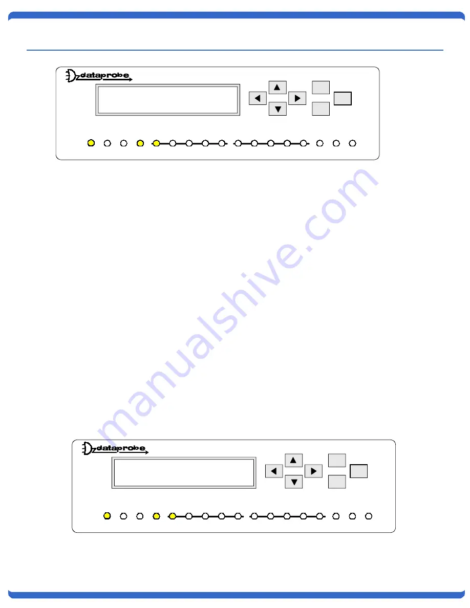
Each setting is made using the arrow keys to the right of the display.  The display will read “Dataprobe Inc. T-
APS”  when first powering up the unit or any time the unit has been idle for 2 minutes. Touching a front panel 
button will restore the display 
 
To enter the password use the 

UP

 and 

Down

 arrow buttons to select the required character. After locating the 

desired character use the 

Left

 and 

Right

 arrow buttons to move the cursor the next character position. When the 

full password is complete press the Enter button.   
 
After entering the correct password, Setup Menu appears.   
 
Scroll up or down to the desired feature and press Enter to select. 
 
The Asterisk (*) indicates the currently selected option. To change options, use the left or right arrow then press 
Enter. 
 
To return to the Setup Menu again, press Escape.  

ESC

Enter

Auto Protection Switch

1 SET T1/E1 MODE
2 SET WORK MODE

T-APS

ACO

Run    1:1

E1

T1

L1

L2

LOS OOF

AIS

RAI

Fail

1:1 CHK

ACO

LOS OOF

RAI

AIS

ESC

Enter

Auto Protection Switch

PASSWORD:

T-APS

ACO

Run    1:1

E1

T1

L1

L2

LOS OOF

AIS

RAI

Fail

1:1 CHK

ACO

LOS OOF

RAI

AIS

Summary of Contents for T-APS 1130052

Page 1: ...and Ethernet connectivity for remote access and is SNMP compatible Local and remote alarm notifications are provided for circuit failures 2 Features T1 or E1 interface selectable 1 1 1 1 or Blind aut...

Page 2: ...ath T1 E1 Protection Path T APS T APS ESC Enter Auto Pro tect ion Sw itch Dataprobe Inc T APS T APS ACO Ru n 1 1 E1 T1 L1 L2 LOS OO F AIS RAI Fail 1 1 CHK ACO LOS OO F RAI AIS ESC Enter Auto Pro tect...

Page 3: ...NMP Network I EARTH GND 48V ALARM ON OFF POWER RJ45 PIN Assignments CPE L1 and L2 CPE Customer Premise Equipment L1 Line 1 Active Path L2 Line 2 Protection Path Pin Assignment 1 Receive Data 2 Receive...

Page 4: ...n B LOOK IN Setting the LOOK IN Function On will indicate the CPE side fault by showing L1 light on and 1 1 LED light blinking In the event of L2 protection path fault the fault is also indicated as L...

Page 5: ...d use the UP and Down arrow buttons to select the required character After locating the desired character use the Left and Right arrow buttons to move the cursor the next character position When the f...

Page 6: ...Can be used with other APS type devices Monitor for loss of CO signals on Active line and transfers to Protection path Provides Protection path status from LOS only when the path is not in use Blind 2...

Page 7: ...MD CAS CCS CAS C CCS C 4 SET LINE CODE T1 Setting Selections B8ZS AMI E1 Setting Selections HDB3 AMI 5 RX SENSITIVITY NETWORK Selections LONG SHORT LONG T1 Setting Sensitivity is 36 dB E1 Setting Sens...

Page 8: ...l occur Use the selection 5 to perform switching A SELECT ACTIVE PATH Selections PATH 1 PATH 2 B ENABLE LOOK IN MODE Selections ENABLE DISABLE T APS Master and Slave unit will do a checking function t...

Page 9: ...preset threshold value it will then switch back from PROTECTION PATH to the ACTIVE PATH E SET FRAME ALARM RATIO Selections 1E 5 1 x 10 5 1E 4 1 x 10 4 1E 3 1 x 10 3 1E 2 1 x 10 2 1E 1 1 x 10 1 Once t...

Page 10: ...event of receiving bit errors LOS OOF AIS RAI Pressing the ACO bottom on the display will stop the BUZZER Setting BUZZER OFF will disable the BUZZER function K SET RECOVERY TIME Selections 00 to 99 M...

Page 11: ...DATE MM DD YY Month Day Year R SET CURRENT TIME HH MM SS Hour Minute Second S SET PASSWORD Default Password PASS T USE FACTORY DEFAULTS Selections YES NO U SHOW CURRENT LINE Displays either Line 1 or...

Page 12: ...ON Once all errors have been cleared T APS will switch back to working path and the NC contacts will return to an open state and the Failure LED will then be OFF NC Contact Open conditions 1 Power su...

Page 13: ...erminal emulation software like Hyperterminal The RS 232 port settings are 9600bps 8 Data Bits 1 Stop Bit No Parity 9600 N 8 1 Once you connect to the T APS press the Escape Key Esc to display the pas...

Page 14: ...T APS Users Manual Page 14 8 1 Current Settings The following settings screen will be displayed showing the current configuration This will require the password to be re entered when next accessing t...

Page 15: ...ed decimal format xxx xxx xxx xxx If you are unsure of the entries consult your network administrator Example of MIB Walk sysDescr 0 DisplayString Dataprobe T APS V3 4 sysObjectID 0 ObjectIdentifier 1...

Page 16: ...feet LED Status Display RUN 1 1 T1 or E1 Line 1 and Line2 LOS OOF AIS RAI Fail ACO ALARM Contacts Form C relay 0 5A 30VDC MAX Automatic Switching Parameter Programmable Code Violation 10 3 10 6 CRC Er...

Page 17: ...at 201 934 5111 to receive a Return Materials Authorization RMA Number prior to sending any equipment back for repair Include all cables power supplies and proof of purchase with shipment THIS WARRAN...

Reviews: