background image


V110120E 

iBoot-G2+   

Page 11 

6. Web Browser Operation 

6.1. Password 

Protection 

iBoot-G2+ uses two username/password credential sets, one for normal 
power control (User) and one that also provides access to the setup functions 
(Admin).   
 
Default Credentials: 

Role  

Username (fixed) 

Password (user set) 

Administrator admin 

admin 

User user 

user 

 
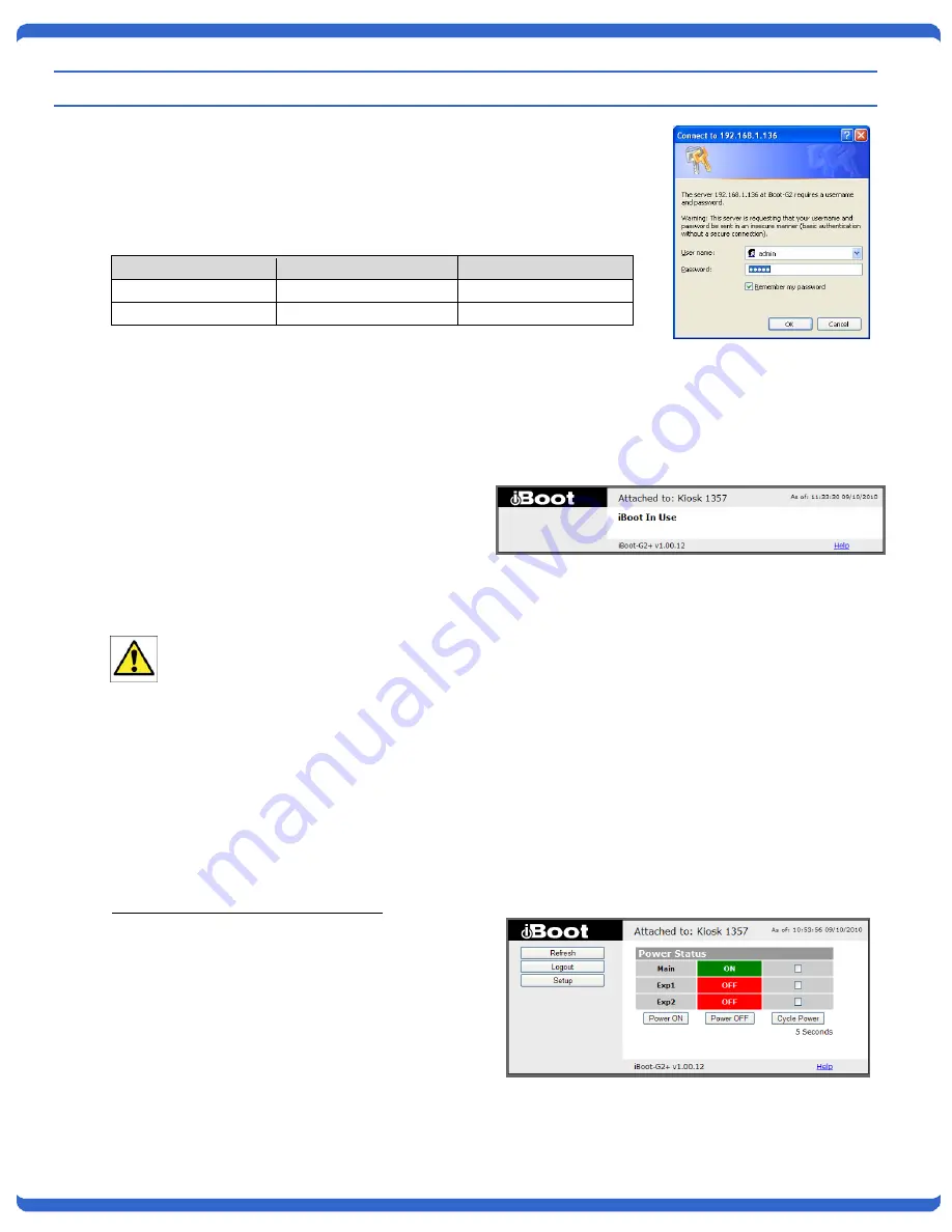
Open your browser and enter the IP address of iBoot-G2+ into the address bar.  If you have changed the IP 
address by any of the methods described, enter that address, otherwise, use the default IP address 
192.168.1.254 
 
Enter the username and password as prompted.  When the proper username/password is received the Control 
and Status Page is displayed. 
 
iBoot-G2+ uses an inactivity timer for security.  
This timeout is user selectable from 0 to 99 
minutes.   Setting to zero disables the timeout 
feature.  When there is no activity for the set time 
in minutes, the user is logged automatically logged 
out and the username and password will need to 
be entered again for access.    This  is  to  prevent 
accidental lockout by leaving the user logged in.   
 

As the iBoot-G2+ allows only one Web user logged in at any time, use caution when disabling the 
timeout feature, as it is possible to lock out other users by forgetting to logout.  Closing the browser 
will not log the user out and will lock out web access.   If you do become locked out, access the iBoot-
G2+ via Telnet and reboot the unit, or press the reset button (see Section 11) 
 

6.2. 

Control and Status Page 

Once the user is validated, the Control and Status is displayed. (Only one person can be connected to the 
iBoot-G2+ at a time.)  
 
The look of the Control and Status page will be determined by which options are selected for the Expansion, 
AutoPing and Heartbeat.   
 

Expansion Set for  iBoot-Exp Mode: 

The Control and Status page will show the On or 
Off status of each of the three manageable outlets, 
Main, Exp1 and Exp2. 
 
To control the power, select the desired outlets and 
click on the appropriate button.  If an outlet is linked 
to the Main outlet, an 

L

 will replace the checkbox 

(as shown for Exp1) and it will be managed in sync 
with the Main Outlet. 
 
During power cycling, the Power Status bar will 
indicate the temporary status, with a blue background.  Once the cycle is complete, the status bar will revert to 

Summary of Contents for iBoot G2+

Page 1: ...able The iBoot G2 provides you the ability to reboot crashed devices with the click of a mouse Be sure to read up on all the features of the iBoot G2 Including Web Based setup and control Telnet setup and control Event Scheduling Set power actions on regular intervals Expansion Add low cost iBoot EXP units for up to three outlets controlled AutoPing Automatic monitoring and action for failed equip...

Page 2: ...2 prong adapter at the receptacle use of this type adapter may result in risk of electrical shock and or damage to this product 9 Do not allow anything to rest on the power cord Do not locate this product where the cord will be abused by persons walking on it 10 Do not overload wall outlets and extension cords as this can result in the risk of fire or electric shock 11 Never push objects of any ki...

Page 3: ...ings and to save on wear and tear Power up alert devices like sirens lamps messages or control environmental system like heaters coolers pumps etc 3 2 Multiple Control Options In addition to the Web control capabilities iBoot G2 features several other means to operate automatically or under computer control AutoPing The AutoPing feature allows iBoot G2 to automatically detect failed equipment and ...

Page 4: ...and control additional devices Inputs on the expansion ports can be used to monitor alarm contacts environmental sensors relays and switch closures The outputs can drive relays for process control security and environmental controls iBoot G2 uses Dataprobe Exchange Protocol DxP to communicate with other Dataprobe devices to allow transport of GPIO information across the network DxP protocol is ava...

Page 5: ...an IEC320 receptacle and detachable power cord an IEC to IEC extension cord can be used The iBoot G2 can be connected to a power strip to allow simultaneous control of multiple devices Make sure that the combined load of all controlled devices does not exceed 12 Amps for 105 125VAC or 10 Amps for 210 240VAC An LED Indicator next to the Switched Outlet will be On to indicate that the power is On at...

Page 6: ...minals are tightened securely and that there are no loose strands of cable or excessive stripped wires Connecting to iBoot Exp Terminal blocks are connected pin to pin with the iBoot Exp as shown Connect Function iBoot G2 iBoot Exp Power V Power Out V Power In Feedback I Input O Output Ground G Ground G Ground Command O Output I Input Expansion units iBoot Exp are shipped with a cable for easy con...

Page 7: ...he USB port install the USB driver Download the driver at http dataprobe com support iboot html USB Driver Installation Run ibootG2Driver exe prior to connecting the iBoot G2 to the USB port of the PC Connect the USB iBoot G2 to a USB port of the PC The PC will discover the iBoot G2 and assign a COM port To find the COM port go to Control Panel System Device Manager Ports COM LPT The com port assi...

Page 8: ...rdware Installing the Wall Mounting Kit DIN Rail Mounting 1 Remove the four mounting screws from the underside of the unit Do not disassemble the unit 1 Install the Wall Mounting Kit as shown 2 Install the wall mounting ears to the unit using the screws removed in Step 2 2 Install the DIN rail clips using the four screws provided 3 The unit is ready for wall mounting 3 Ready for DIN rail mounting ...

Page 9: ...CP server on your network If the IP address was assigned by a DHCP server no changes to the IP Address are required The IP address field also indicates the port for web access that is used by the iBoot The standard port for web browser control is factory default Port 80 Change the IP Address 1 Click on the row containing the iBoot G2 to be set The row will become highlighted 2 From the menu select...

Page 10: ... what address is assigned to the iBoot You can lock the iBoot G2 to the current address by selecting IP Mode Static without changing the addresses Set the IP Mode either by using the web setup page or via Telnet commands If you set the IP address using another method the address becomes static To return iBoot G2 to dynamic addressing using DHCP select DHCP mode in Network Setup and reboot the unit...

Page 11: ...t by leaving the user logged in As the iBoot G2 allows only one Web user logged in at any time use caution when disabling the timeout feature as it is possible to lock out other users by forgetting to logout Closing the browser will not log the user out and will lock out web access If you do become locked out access the iBoot G2 via Telnet and reboot the unit or press the reset button see Section ...

Page 12: ... connecting with the Admin credentials reset buttons for the Trigger counters are provided Heartbeat Enabled If the Heartbeat feature is enabled the page will display the current status OK or Fail of the Heartbeat with a counter showing how many times the Action was triggered If connecting with the Admin credentials reset buttons for the Trigger counters are provided Navigation Buttons Refresh Use...

Page 13: ...eb user logged in at any time use caution when disabling the timeout feature as it is possible to lock out other users by forgetting to logout Closing the browser will not log the user out and will lock out web access If you do become locked out access the iBoot G2 via Telnet and reboot the unit or press the reset button 7 2 Expansion Settings Mode Set iBoot Exp or Independent I O mode iBoot Exp d...

Page 14: ... is 9105 then use the address http 192 168 1 254 9105 Telnet Port This setting is used to allow access to the iBoot G2 via telnet by ports other than standard 23 DxP Port This setting is used to allow access to the iBoot G2 via Dataprobe Exchange Protocol DxP via ports other than standard 9100 Enable DxP Control This setting enables external devices to control the iBoot G2 via DxP protocol Enable ...

Page 15: ...work device and powers up alarm or redundant system when there is no response Ideal for Hot Standby Servers Environmental Control Alert for any Network Failure iBoot G2 supports three independent AutoPing channels each controlling either the Main power or either of the two Expansion ports The first AutoPing channel can be programmed with two separate IP Addresses with logical AND OR comparisons to...

Page 16: ... device Power Cycle Once Upon triggering iBoot G2 will cycle power one time It will not cycle again automatically until the ping response returns and is lost again With AutoPing operational the main iBoot G2 page will display the current status of this feature The status will be OK to indicate that iBoot G2 is receiving responses to the ping or that the fail counter has not yet been exceeded If th...

Page 17: ...run as a tray applet that will transmit heartbeats at a steady interval to an iBoot A Windows dll file is also available for use by Windows applications The Heartbeat Protocol will allow developers to imbed this capability directly into their software products 7 7 Heartbeat Settings Source Select the source of the heartbeat either USB Network or None heartbeat not used When using the Network enter...

Page 18: ...eartbeat is turned off Make sure your Heartbeat frequency is longer than the time required to reboot your device Power Cycle Once Upon triggering iBoot G2 will cycle power one time It will not cycle again automatically until the heartbeat returns and is lost again Outlet Select Main for the internal power outlet or Exp1 Exp 2 for either of the two expansion ports 7 8 Using Heartbeat Monitor With H...

Page 19: ...urs or Minutes Action Set the event Action On Off or Cycle Click Save to save the current settings Click Clear to delete any current schedule Note All of the Schedule Settings require a reboot of the iBoot G2 after clicking Save A Reboot button will appear at the bottom of the page The new settings will not take effect until the unit is rebooted Reboot will not affect the power position of the iBo...

Page 20: ...it No Flow Control Once the connection is made send Enter When connection is successful the User prompt is displayed Enter user or admin and press Enter The prompt will change to Password Enter the admin or user password and press Enter The prompt will change to iBoot This indicates successful login Enter commands as needed When done enter the logout command 8 2 iBoot G2 CLI Syntax Command Descrip...

Page 21: ...ess 192 168 1 203 Relay 3 set expansion mode exp io This command sets the mode for the expansion ports to either iBoot Exp or External I O exp set expansion exp1 exp2 link yes no This command sets the Exp1 or Exp2 to be linked to the main outlet for simultaneous control This command takes effect only when expansion mode is exp no set expansion exp1 exp2 ipaddress dotted decimal This command sets t...

Page 22: ...ich is TCP 9100 set dxp port 0 65535 This command sets the port that the iBoot G2 s DxP protocol service listens for incoming connections on When set to 0 the Protocol service is disabled Note At least one of the above MUST NOT be 0 The CLI will protect against all 3 from being set to 0 9100 set dxp control enable disable This command allows the main and expansion ports to be controlled using Data...

Page 23: ...gs Source USB Status Trigger Count Frequency 10 OK 0 Fail Count 3 Action Cycle Once Outlet Main set heartbeat source none usb network This command sets the source for the heartbeat Either USB or Network None set heartbeat frequency 1 999 This command is used to set the frequency in seconds How often the iBoot G2 expects the heartbeat 10 set heartbeat failcount 1 999 This command is used to set the...

Page 24: ...led action s start date set event 1 8 time hh mm This command is used to set the time the scheduled action will occur in 24 hour format set event 1 8 repeat minute hour day This command is used to set the increments for repeating scheduled actions set event 1 8 mult 0 999 This command sets how often the event will repeat the number of increments as set by the command above before the next event se...

Page 25: ...the release notes for the upgrade before making changes to you iBoot G2 1 Insure that the Upgrade Enable checkbox is checked in the Network Setup web page of the iBoot G2 2 Run the Device Management Utility available at the link above If the iBoot G2 you would like to upgrade is not visible in the list box either Select Device Discover from the menu to locate iBoot G2 units on the local network or...

Page 26: ... expected Use the pushbutton as follows Action Result Momentary Soft Reset Will not change outlet status 5 Seconds push Reset to Factory Defaults Hold the button in until the Outlet LED is blinking then release Hold in while and Power up the iBoot Recovery Mode Allows upload of new firmware to Factory default IP Address 192 168 1 254 ...

Page 27: ...12 VDC power out from the iBoot G2 Maximum current 100 mA Feedback I Input Input for status signals Dry Contact input or Open Collector Ground G Ground Signal Ground for Input and Output Command O Output 2N3904 NPN Transistor 100 mA Maximum 12 4 Compliance UL cUL UL60950 Listed I T E File No E225914 CE Directives 89 336 EEC 92 31 EEC and 93 68 EEC EN 60950 3rd Edition EN 55022 1998 Class B FCC Par...

Page 28: ...e at 201 934 5111 to receive a Return Materials Authorization RMA Number prior to sending any equipment back for repair Include all cables power supplies and proof of purchase with shipment THIS WARRANTY DOES NOT APPLY TO NORMAL WEAR OR TO DAMAGE RESULTING FROM ACCIDENT MISUSE ABUSE OR NEGLECT SELLER MAKES NO EXPRESS WARRANTIES OTHER THAN THE WARRANTY EXPRESSLY SET FORTH HEREIN EXCEPT TO THE EXTEN...

Reviews: