background image

QUICK REFERENCE GUIDE   

5

Wall/Desk Mount

The Wall/Desk Mount is an accessory part to which the scanner can be
attached. The accessory can be mounted horizontally to a desk,
countertop, or table using screws or a gooseneck stand. It can also be
mounted vertically to a wall using screws, or to a VESA mount. 

Installation Instructions

1.

Determine the mounting location. While deciding on the best 
position, keep in mind the best way to route the scanner cables. 
You may need to drill a hole for them.

2.

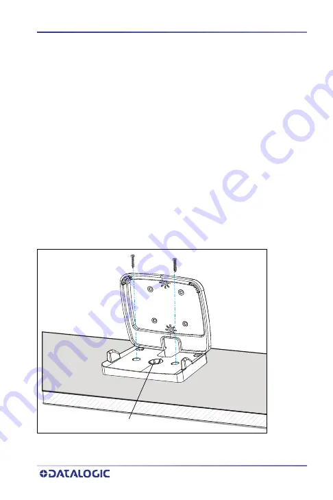
Use two #8 screws (sheet metal screws are preferred) to securely 
fasten the Mount in the position desired, as shown in the 
following figures.

Desk (Horizontal) Mounting

Figure 7. Desk Mount

Gooseneck Mount location

#8 screws

Summary of Contents for MAGELLAN 3410VSi

Page 1: ...QUICK REFERENCE GUIDE MAGELLAN 3410VSi Omni Directional Imaging Scanner ...

Page 2: ...site www datalogic com If you visit our website and would like to make comments or sug gestions about this or other Datalogic publications please let us know via the Contact page Disclaimer Datalogic has taken reasonable measures to provide information in this manual that is complete and accurate however Datalogic shall not be liable for technical or editorial errors or omissions contained herein ...

Page 3: ...hing the scanner 8 Bottom Cover Tilting Riser 9 Mounting the Riser 10 How to Scan 11 Scanner Button 11 Camera Button 12 LED and Beeper Indicators 13 Beeper Indicators 14 Troubleshooting 14 Error Codes 15 Programming 16 Interface Selection 16 Imaging Features 18 Camera Button Mode 18 Image Destination 19 Cell Phone Mode 20 Cell Mode Percent 21 Cleaning 22 Manufacturer Approved Cleaning Materials 23...

Page 4: ...iv MAGELLAN 3410VSI NOTES ...

Page 5: ...rs and begin using your scanner For more details and programming information reference the Product Reference Guide PRG which is available for viewing and download from the Datalogic website www datalogic com FEATURES Figure 1 Scanner Features Front View Wall Desk Mount Scanner Button Camera Button Scan Cable Connector Cover FRONT Window ...

Page 6: ...atures Back View Figure 3 Scanner Features Bottom View Cable Routing Area Serial Number Label Regulatory USB Micro B MicroSD Card Port Label Service Access USB Aux Port Power Host Port Cavity for EAS Connection Wire MicroSD Card USB Micro B ...

Page 7: ... is powered only by the standard USB cable as shown in Figure 6 on page 4 an auxiliary scanner will not be supported After the scanner has fully powered up and indicates that it is ready for operation scan some known good bar code samples to verify correct operation The scanner should beep and or flash its good read LED1 and send the bar code data to the host or terminal If not use the Troubleshoo...

Page 8: ...Terminal NOTE This cable or similar will not support a USB peripheral The system must be powered by 12V in order for a peripheral to be attached to the AUX USB PORT U S B R S 232 RS 232 and USB Cables Powered by AC Adapter To Terminal PC U S B To Terminal PC USB Type A Power Off the Terminal ...

Page 9: ...cally to a wall using screws or to a VESA mount Installation Instructions 1 Determine the mounting location While deciding on the best position keep in mind the best way to route the scanner cables You may need to drill a hole for them 2 Use two 8 screws sheet metal screws are preferred to securely fasten the Mount in the position desired as shown in the following figures Desk Horizontal Mounting ...

Page 10: ...6 MAGELLAN 3410VSI Figure 8 Desk Mounting Dimensions Wall Vertical Mounting Figure 9 Wall mount 63 41 92 5 ALL UNITS ARE IN MM 50 mm 8 screws screw holes VESA mount ...

Page 11: ...QUICK REFERENCE GUIDE 7 Figure 10 Wall Vertical Dimensions 75 42 5 130 2 135 5 50 55 132 1 ALL UNITS ARE IN MM ...

Page 12: ...the scanner diagonally down seating the L Bracket tabs on the Mount into the scanner s slots 2 Push the scanner down to snap into place Detaching the scanner 1 Tilt the top of the scanner forward separating it slightly from the back of the mount 2 Pull up to detach If oriented correctly it should come out easily Figure 11 Attaching Detaching scanner from Mount Scanner Wall Desk Mount ...

Page 13: ...and the cover will release from the scanner Attach the Tilting Riser by snapping into the place of the Bottom Cover Figure 12 Attaching the Tilting Riser When removing the Tilting Riser note that the snaps on the riser may be tight If necessary use a coin or other flat tool in the provided slots as shown above to separate the snaps and release the riser Bottom Cover Tilting Riser Coin Slot ...

Page 14: ...ELLAN 3410VSI Mounting the Riser The Adjustable Riser can be mounted to a flat surface using two 8 screws Figure 13 Mounting the Tilting Riser Figure 14 Tilting Riser Dimensions 64 2 23 8 ALL UNITS ARE IN MM ...

Page 15: ... it is pressed NOTE Volume changes made using the Scanner Button are lost when the scanner is powered down and are reset to the configured setting If you wish to permanently change the volume use the programming labels in the Product Reference Guide PRESS DURATION FUNCTION COMMENT Momentary when scanner is asleep Wakes scanner from Sleep Mode Alternatively the scanner can be awakened by Moving an ...

Page 16: ...per sounds Increments tone Press the button for approximately 2 seconds then release Each time this is done the beeper will sound at one of three tones Stop when the desired tone high medium or low is sounded 4 Seconds Scanner Diagnostics Modea This mode allows system support personnel to troubleshoot problems with the scanner and is used to determine if it can read bar codes Press the button for ...

Page 17: ... green flash Indicates a bar code has been read and decoded Scanner Ready Constant dim green The scanner is ready for operation Sleep Mode Green LED flashes every 2 seconds 10mS on 1990mS off The scanner is in Sleep Mode To wake the scanner up move an object in front of its window or press the Scanner Button This indication is optionally configurable and may have been programmed to behave differen...

Page 18: ...tions Varies depending upon the feature s being configured The Beeper will sound as programming bar code labels are scanned indicating progress during scanner configuration PROBLEM SOLUTION Scanner does not power on Exchange the power supply with a known good power supply and retest operation No communication with the host Consult your technical support personnel or refer to your host system manua...

Page 19: ...neous to the beeps The table below describes what these codes mean and what action should be taken for each If the scanner still does not function properly consult the Product Reference Guide PRG or contact your local supplier or Datalogic Customer Support Services a Reading of the various bar code symbologies can be independently enabled or disabled in the scanner NUMBER OF LED FLASHES BEEPS ERRO...

Page 20: ...er scanning the programming label for the desired interface scan the START END barcode a second time to accept your changes exit Programming Mode and return the scanner to normal operation Select other options and customize your scanner with programming barcodes available in the PRG or use the Datalogic Scanalyzer utility available on the Datalogic website Interface Selection NOTE In the following...

Page 21: ...ICK REFERENCE GUIDE 17 USB OEM USB Keyboard USB COM Interface NOTE Reference the Product Reference Guide PRG or Datalogic Scanalyzer utility for additional options START END 000145 CR 000135 CR 000147 CR ...

Page 22: ... Imaging Features See the PRG for more information on these features Camera Button Mode Scan one of the bar codes below to enable or disable the camera button START END Camera Button Mode Disable Camera Button Mode Enable ...

Page 23: ...UIDE 19 Image Destination Specifies the destination for pictures images taken with a camera button press START END Image Destination Disable Image Destination SD card Image Destination Host port 500 CR 042501 r 042503 r ...

Page 24: ... 3410VSI Cell Phone Mode Enables disables mobile phone barcode reading START END Cell Phone Mode Enable Toggle Cell Phone Mode Enable Always On Cell Phone Mode Enable Timer Expiration 046700 CR 046702 CR 046701 CR ...

Page 25: ...ne mode must be enabled for this to be active NOTE Settings above 10 will slow down read performance on printed barcodes START END Cell Mode Percent 5 Very Low Cell Mode Percent 10 Low Cell Mode Percent 20 Medium Cell Mode Percent 30 Med High Cell Mode Percent 50 High 047100 CR 047101 r 047102 r 047103 r 047104 r ...

Page 26: ...rasive mild water based cleaner to wipe away stains smudges fingerprints spills etc from the scan window and exterior surfaces See the next page for a list of Manufacturer Approved Cleaning Materials CAUTION DO NOT use abrasive cleaning agents or abrasive pads to clean this product Harsh chemicals disinfectants and cleansers can cause damage which will adversely affect scanning persformance CAUTIO...

Page 27: ...nation with other cleaning agents will void the manufacturer s warranty APPROVED CLEANERS Hydrogen Peroxide not to exceed a 3 solution Chlorine bleach not to exceed a 0 25 solution Mild detergent and water lsopropyl Alcohol not to exceed a 70 solution CAUTION Use of above cleaners in combination with each other is not recommended and may constitute a health hazard Follow all specified safety preca...

Page 28: ...e unit consumable items 7 use of counterfeit or replacement parts that are neither manufactured nor approved by Datalogic for use in Datalogic manufactured Products 8 any damage or malfunctioning caused by non restoring action as for example firmware or software upgrades software or hardware reconfigurations etc 9 loss of data 10 any consumable or equivalent e g cables power supply batteries etc o...

Page 29: ... 25 GOING GREEN Thank you for using the bar code mask on the opposite side of this page This manual has been formatted to minimize the quantity of pages needed to provide the programming bar codes available for this product ...

Page 30: ...is page and remove it from the manual as indicated to create a sleeve through which bar codes can be individually viewed and scanned It is important that only one bar code at a time be presented to the scanner Bar Code Mask Sheet Bar Code Manual folded ...

Page 31: ......

Page 32: ... in any form or by any means or for any purpose without the express written permission of Data logic S p A and or its affiliates Datalogic and the Datalogic logo are registered trademarks of Datalogic S p A in many countries including the U S and the E U Datalogic S r l Via S Vitalino 13 40012 Lippo di Calderara di Reno Bologna Italy Tel 39 051 3147011 Fax 39 051 3147205 www datalogic com 82011780...

Reviews: