Electrical Installation
26
DX8210 Barcode Scanner
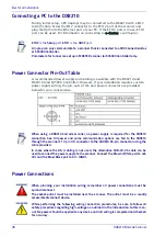
Connecting a PC to the DX8210
During initial setup, a PC (laptop) may be connected to the DX8210 with a M12
to RJ45 cable. Screw the M12 connector to the ETH 2 port of the scanner and
plug the RJ45 into the Ethernet port of your PC. If the ETH 2 port is in use, ETH 1
port can be used. For information on connecting to e-Genius,
see Chapter .
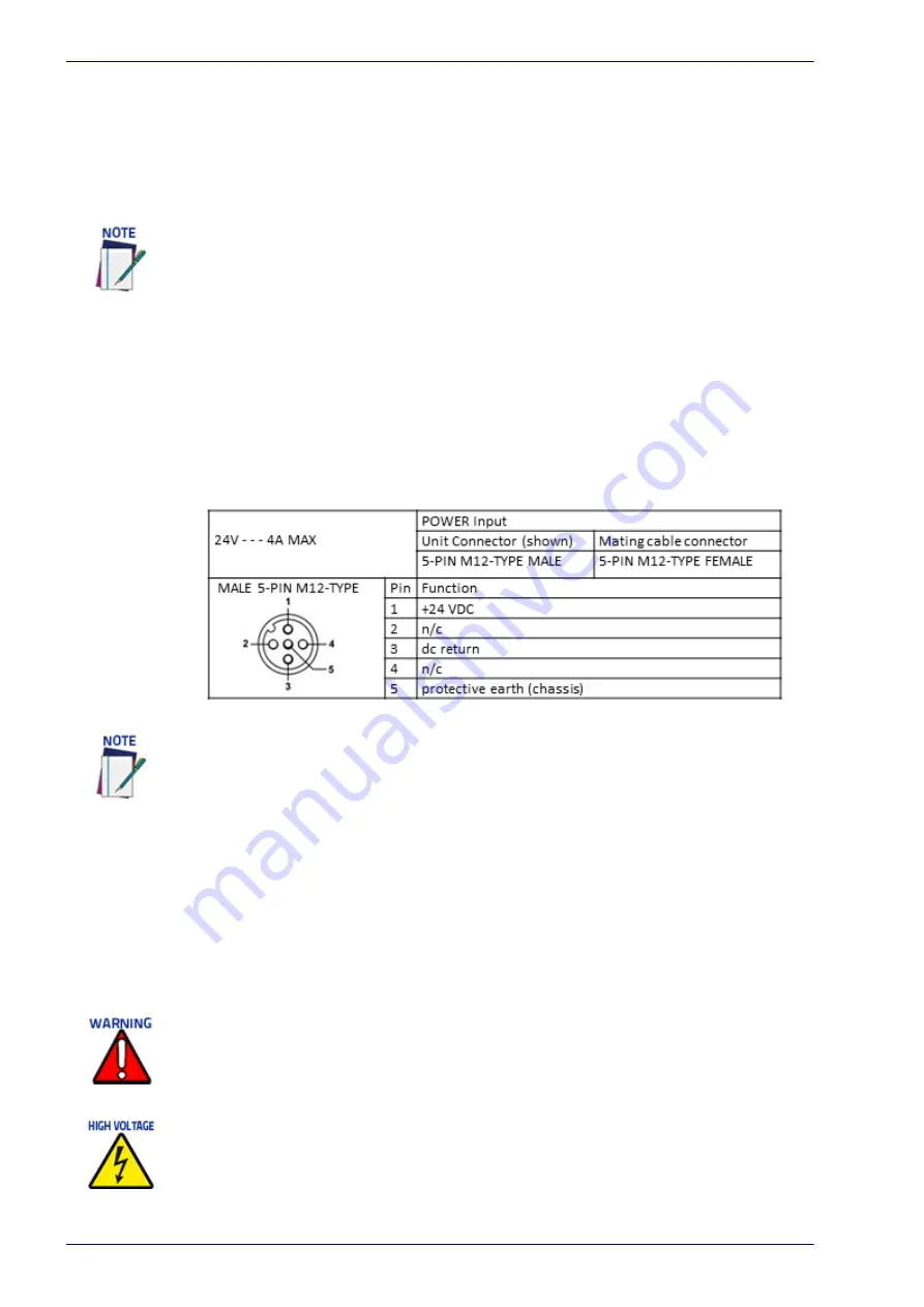
Power Connector Pin-Out Table
A recommended power supply and cabling is available with the DX8210 and
DX8210 (and SC5000 Controller). However, if your installation requires custom
power supply wiring, the pin-outs of the unit power connector are provided
below for your convenience.
Power Connections
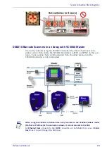
ETH2
is the
Setup
port,
ETH1
is the
HOST
port.
A laptop can only communicate to a scanner that is connected to a CBX Connection Box
or SC5000 Controller.
Parameters for tunnel are set up in MASTER scanner (or SC5000 Controller) only.
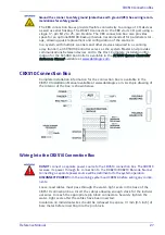
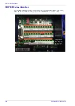
When using a DX8210 barcode scanner, no power supply is required for the CBX510
connection box. All power and some communication options are fed to the CBX510
through the scanner’s 17-pin I/O connector to the CBX510 25-pin connector using the
cable provided.
In cases where the AS-I cabling is not used, the alternative CAB-LP-05 cable can be
used to connect the power supply to the scanner. Connect the Brown/White pair to +24
Vdc and the Blue/Black pair to 0 V- (GND).
When planning your installation wiring, remember all power connections must be
quick-disconnect.
The socket-outlet must be installed near the scanner. The outlet must be a readily
accessible disconnect device.
While performing the following wiring connection procedures, be sure to follow all
safety procedures regarding high-voltage as outlined in the Introduction to this man-
ual. No power should be applied to any device until all wiring is completed and checked
for accuracy.
Summary of Contents for DX8210
Page 1: ...DX8210 Reference Manual Omnidirectional Barcode Scanner ...
Page 31: ...Installation Reference Manual 19 Small Side Mounted L Bracket Options ...
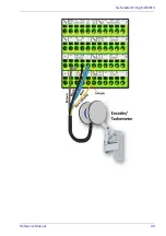
Page 45: ...Tachometer Wiring to CBX510 Reference Manual 33 ...
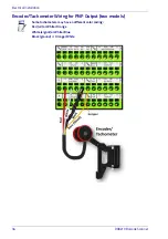
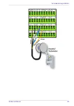
Page 47: ...Tachometer Wiring to CBX510 Reference Manual 35 ...
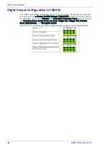
Page 49: ...Digital Output Configuration to CBX510 Reference Manual 37 Unpowered Outputs Powered Outputs ...
Page 268: ...Barcode Scanning Features 256 DX8210 Barcode Scanner DX8210 2100 0 25 mm 10mil ...
Page 269: ...Reading Diagrams Reference Manual 257 DX8210 2100 0 30 mm 12mil ...
Page 270: ...Barcode Scanning Features 258 DX8210 Barcode Scanner DX8210 2100 0 38 mm 15mil ...
Page 271: ...Reading Diagrams Reference Manual 259 DX8210 2100 0 50 mm 20 mil ...
Page 272: ...Barcode Scanning Features 260 DX8210 Barcode Scanner DX8210 4100 0 38 mm 15 mil ...
Page 273: ...Reading Diagrams Reference Manual 261 DX8210 4100 0 50 mm 20 mil ...
Page 274: ...Barcode Scanning Features 262 DX8210 Barcode Scanner DX8210 4200 0 25 mm 10 mil ...
Page 275: ...Reading Diagrams Reference Manual 263 DX8210 4200 0 30 mm 12 mil ...
Page 297: ...Reference Manual 285 ...
Page 298: ......
Page 299: ......

