


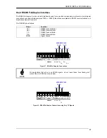
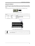


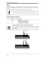


CBX800 INSTALLATION MANUAL
28
TYPICAL LAYOUTS
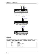
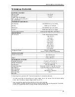
The following figure shows the general system layout.
Figure 38 – General System Layout
The general system layout allows the CBX800 Gateway to connect any serial device (Hand-Held Reader, 6K,
8KA Scanner, Matrix-2000, etc.), collect its information and send it to a Host over a serial or TCP/IP or Fieldbus
interface.
Generally the external system Host is connected to the CBX800 Host interface. The reading device connects to
the 25-pin connector (Source). The reading device auxiliary interface signals are also available on the internal
spring clamp connectors.
The ID-NET interface allows any serial device to be connected to a Full-Speed ID-NET™ compatible network.
The dotted lines in the figure refer to optional hardware configurations.
A portable PC can be quickly connected to the CBX800 Auxiliary port through the internal 9-pin MUX/GWY
connector for CBX800 configuration.
Likewise the portable PC can be quickly connected to the Source Auxiliary port through the internal 9-pin Source
connector for reader configuration.
After making system cabling and switch settings, switch ON the CBX800 power switch (see Figure 4). The Power
LED turns on (blue) when the power connection has the correct polarity. The Power LED turns on (red) in case of
wrong polarity.
After CBX800 configuration and system functioning has been verified, close the CBX800 using the four cover
screws.
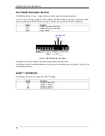
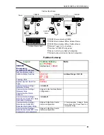
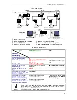
Reading Device
PWR
CBX800
Source
Auxiliary
Interface
I/O
Gateway to ID-NET™
Gateway to Host
or
> BMxxx
Fieldbus
> BM200 TCP/IP
or
Serial RS232/RS485
Auxiliary
Interface
HOST