CBX500 INSTALLATION MANUAL
10
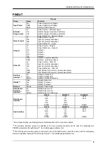
PINOUT
Pinouts
Group Name
Function
Input Power
Vdc
Power Supply Input V
GND
Power Supply Input Voltage -
Earth
Protection Earth Ground
External
Trigger Input
+V
Power Source – External Trigger
I1A
External Trigger A (polarity insensitive)
I1B
External Trigger B (polarity insensitive)
-V
Power Reference – External Trigger
Generic Input
+V
Power Source – Inputs
I2A
Input 2A (polarity insensitive)
I2B
Input 2B (polarity insensitive)
-V
Power Reference – Inputs
Outputs
+V
Power Source – Outputs
-V
Power Reference – Outputs
O1+ Output
1+
O1- Output
1-
O2+ Output
2+
O2- Output
2-
Other I/O
O3A
Output 3A / 3+ (Pass Through)
O3B
Output 3B / 3- (Pass Through)
+V
Power Source – Other I/O
I3A
Input 3A / 3+ (pass through)
I4A
Input 4A / 4+ (pass through)
-V
Power Reference – Other I/O
I34B
Input 3B / 3- (common) (pass through)
I34B
Input 4B / 4- (common) (pass through)
Auxiliary
Interface
TX
Auxiliary Interface TX
RX
Auxiliary Interface RX
SGND
Auxiliary Interface Reference
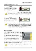
ID-NET™
REF Network
Reference
ID+ ID-NET™
network
+
ID- ID-NET™
network
-
Network
Shield
Network Cable Shield
RS232 RS485FD
RS485HD
Main
Interface
TX
TX+
RTX+
RTS
TX-
RTX-
RX
*RX+
CTS
*RX-
SGND
SGND
SGND
The input power signals
Vdc
,
GND
and
Earth
as well as the network signals
REF
,
ID+
,
ID-
and
Shield
; and
RTX+
,
RTX-
and
SGND
are repeated to facilitate system cabling. In this way
the power and network busses can enter and exit the CBX500 from different spring clamps
but be physically connected together.
*
Do not leave floating, see Reading Device Reference Manual for connection details.


