background image

DKM-40

7 Kullanım Kılavuzu                                                                                    V-1.1


9


The 

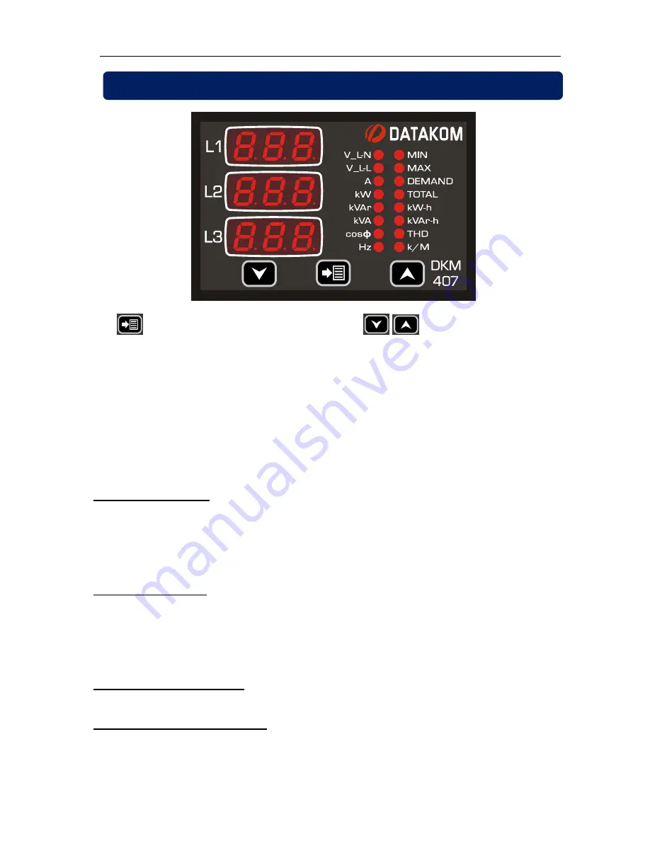
 button will select the display context and 


 buttons will navigate 

between possible values of this context. 
 

Kilo/Mega (k/M) led

 will turn on if the displayed value is in kA/kV/MW/MVA/MVAr. 

TOTAL led

 will turn on when displaying total values. 

 
Normally, the led indicating the values on display will be on. Other leds will turn off. If total 
working hours is displayed then only the TOTAL led will turn on.  

When displaying voltage, current, THD, power factor, etc.. each display will show the 
value related to one phase. When total values are displayed, depending on the length of 
the data to display, all 3 displays may be used. 

Display of currents: 

If the greatest current value to display is larger than 999A then the 

k/M

 (kilo/mega) led will turn on, otherwise it will turn off. When the k/M led is off, if the 

greatest current value is below 100A then currents will be displayed with 0.1A precision, 
otherwise they will be displayed with 1A precision. When the k/M led is on, if the greatest 
current value is below 10kA then currents will be displayed with 0.01kA precision, 
otherwise they will be displayed with 0.1kA precision. 

Display of voltages:

 If the greatest voltage value to display is larger than 999V then the 

k/M

 (kilo/mega) led will turn on, otherwise it will turn off. When the k/M led is off, voltages 

will be displayed with 1V precision. When the k/M led is on, if the greatest voltage value is 
below 10kV then voltages will be displayed with 0.01kV precision, between 10kV and 
99.9kV they will be displayed 0.1kV precision and above 100kV they will be displayed with 
1kV precision. 

Display of kW, kVA, kVAr: 

Depending on the values, they will be displayed with 0.1k or 

1k or 0.01M precision.  

Display of kWh, kVArh, Hours:

 Values are displayed with a precision of 0.1 k (or hour). 

3. DISPLAY NAVIGATION


Summary of Contents for DKM-407

Page 1: ...vides 1 programmable digital input and 1 programmable relay output Input output functions are selected from a list The isolated RS 485 MODBUS RTU data port is not affected by ground potential differen...

Page 2: ...proximity of the unit Fuses must be of fast type FF with a maximum rating of 6A Disconnect all power before working on equipment When the unit is connected to the network do not touch terminals Short...

Page 3: ...ING HIGH AND LOW VOLTAGE LIMITS 4 10 SETTING HIGH AND LOW FREQUENCY LIMITS 4 11 SETTING THE OVERCURRENT LIMIT 4 12 SETTING HIGH AND LOW ACTIVE POWER LIMITS 4 13 SETTING HIGH AND LOW REACTIVE POWER LIM...

Page 4: ...nd specified range Current at measuring terminals beyond specified range Connecting or removing data terminals when the unit is powered up Overload or short circuit at relay outputs Voltage applied to...

Page 5: ...DKM 407 Kullan m K lavuzu V 1 1 5 1 1 FRONT PANEL VIEW...

Page 6: ...e temperature range Use adequate cable section at least 0 75mm2 AWG18 For current transformer inputs use at least 1 5mm2 section AWG15 cable The current transformer cable length should not exceed 1 5...

Page 7: ...DKM 407 Kullan m K lavuzu V 1 1 7 1 4 CONNECTION DIAGRAM...

Page 8: ...and display If all leds are off then actual measurements display HELD PRESSED FOR 5 SEC resets min max values and displays minimum phase to neutral voltages Upper screen or Increase related value conf...

Page 9: ...M led is off if the greatest current value is below 100A then currents will be displayed with 0 1A precision otherwise they will be displayed with 1A precision When the k M led is on if the greatest...

Page 10: ...ters Device Calibration In order to enter the configuration menu hold both MENU buttons pressed for 2 seconds In order to exit the configuration menu hold both MENU buttons pressed for 2 seconds If no...

Page 11: ...o action 1 Reset kWh and kVArh counters Setting this parameter to 1 will reset powermeter counters The parameter value is not stored into memory and reads always 0 Parameter value 0 No action 1 Reset...

Page 12: ...t screen that the unit returns 5 minutes after any key is pressed Setting this parameter to 0 will cancel the default screen Param de eri G stergeler 0 no change 1 Voltages L N 2 Voltages L L 3 Curren...

Page 13: ...default value is 500 5A Acceptable values are 5 5A to 5000 5A This parameter sets the ratio of voltage transformers All voltage and power measurements will be displayed after multiplication with this...

Page 14: ...voltage alarm will occur The factory set default value is 0 Acceptable values are 0 to 12 000volts This parameter sets the low limit for low voltage alarm Only phase to neutral voltages are monitored...

Page 15: ...ts the low limit for low frequency alarm If the parameter is set to 0 then no low frequency alarm will occur The factory set default value is 0 Acceptable values are 0 to 400Hz This parameter sets the...

Page 16: ...ctive power alarm will occur The factory set default value is 0 Acceptable values are 0 to 6500kW This parameter sets the low limit for low active power alarm If the parameter is set to 0 then no low...

Page 17: ...ve power alarm will occur The factory set default value is 0 Acceptable values are 0 to 6500kVAr This parameter sets the low limit for low reactive power alarm If the parameter is set to 0 then no low...

Page 18: ...os alarm will occur The factory set default value is 0 000 Acceptable values are 0 000 to 1 000 This parameter sets the low limit for low cos alarm If the parameter is set to 0 000 then no low cos ala...

Page 19: ...0V AC or DC applied between terminals with the polarity shown in the connection diagram The factory set default value is 0 This parameter sets the detection delay of the digital input signal in milise...

Page 20: ...kWh and kVArh counters increment kWh and kVArh counters reset to zero 2 kWh kVArh hour counters increment no increment 3 kWh kVArh hour counters increment kWh kVArh and hour counters reset to zero 4 H...

Page 21: ...kVArh pulse output 4 High voltage alarm 5 Low voltage alarm 6 High frequency alarm 7 Low frequency alarm 8 Overcurrent alarm 9 Excess active power alarm 10 Low active power alarm 11 Excess reactive p...

Page 22: ...w functions are combined in order to generate the relay output 0 Functions logically OR ed The relay output is active if any of the 4 functions is active 1 Functions loagically AND ed The relay output...

Page 23: ...er defines the delay between an alarm condition occurs and the device gives the alarm It defines also the delay between an alarm condition is removed and the alarm goes off Factory set value is 0 Adju...

Page 24: ...ent node address Factory set value is 0 Adjustment range is 0 to 255 This parameter defines the bit rate used in Modbus communication 0 Baud rate 2400 1 Baud rate 4800 2 Baud rate 9600 3 Baud rate 192...

Page 25: ...Arh then it will function as kWh This parameter determines the amount of kWh or kVArh for 1 pulse output The factory set value is 1 000 kW per pulse The adjustment range is from 0 001 to 10 000 kW or...

Page 26: ...ipment If recalibration is required Please enter 3282 at the bottom display then press button The calibration screen for L1 phase voltage will appear 1 second after the coefficient used for measuring...

Page 27: ...are programmed hold pressed together both buttons for 2 seconds This will exit the configuration menu and perform a display test Check that all displays and leds are turned on Press any button to exi...

Page 28: ...php Data Reading The function 03 read multiple registers will be used for data reading The MODBUS master will send a query The answer will be one of the below A response containing the requested data...

Page 29: ...byte Data Writing The function 06 write single register function 10h write multiple registers are used for data writing A maximum of 32 registers can be written at a time The MODBUS master will send...

Page 30: ...lation 4 CRC high byte CRC calculation Here is a procedure for generating a CRC 1 Load a 16 bit register with FFFF hex all 1 s Call this the CRC register 2 Exclusive OR the first 8 bit byte of the mes...

Page 31: ...ng to below addresses If the value of 3282 is written to the address 16384 then below commands will be accepted during 10 minutes Other commands do not require a password to be written ADRESS NAME DES...

Page 32: ...rd 1 16 Digital input detection delay See chapter 4 15 16 BIT R W unsigned word 1 17 Digital input function See chapter 4 15 16 BIT R W unsigned word 1 18 Relay function 1 See chapter 4 16 16 BIT R W...

Page 33: ...ctive power 32 BIT R O unsigned long 0 1 20514 Total reactive power 32 BIT R O unsigned long 0 1 20516 Phase L1 apparent power 32 BIT R O unsigned long 0 1 20518 Phase L2 apparent power 32 BIT R O uns...

Page 34: ...32 BIT R O signed long 0 1 20564 Phase L3 active power MIN 32 BIT R O signed long 0 1 20566 Total active power MIN 32 BIT R O signed long 0 1 20568 Phase L1 reactive power MIN 32 BIT R O signed long...

Page 35: ...26 Phase L3 reactive power MAX 32 BIT R O signed long 0 1 20628 Total reactive power MAX 32 BIT R O signed long 0 1 20630 Phase L1 apparent power MAX 32 BIT R O signed long 0 1 20632 Phase L2 apparent...

Page 36: ...ges VLL 15 Phase Neutral Voltages VLN Button status register is 16 bits long Each bit shows the status of one button BIT NO DESCRIPTION 0 Set Menu button pressed 1 Set Menu button long pressed 2 Set M...

Page 37: ...long Each bit shows tha status of an alarm BIT NO DESCRIPTION 0 1 2 3 4 High voltage 5 Low voltage 6 High Frequency 7 Low Frequency 8 High current 9 High kW 10 Low kW 11 High kVAr 12 Low kVAr 13 High...

Page 38: ...nputs 0 1VA per phase Current inputs 1VA per phase Relay output 5A 250V AC Digital input Active level 5 30V DC or AC Min pulse 250ms Isolation 1000V AC 1 minute Operating temp range 20 C to 70 C 4 F t...

Reviews: