


7
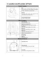
3. Location and Function of Parts
Front of Camera
1
Lens
Built-in 1/2.8” 2.14M Pixel CMOS HD color camera
with white balance control, backlight compensation
settings, automatic gain settings and etc.
2
Tally LED
Tally lamp lights up when tally signal has been
transmitted to the tally signal box.
3
Sensor for Remote Control
Remote controller receiver
Rear of Camera
1
DIP Switch SW2
DIP switch for IRID setting
2
RS422 Communication Port
Remote control of camera via RJ-45 interface
3
HD-SDI OUT
Video signal output: 800mV+-10% 75_ BNC
4
CVBS OUT
Video signal output CVBS 1. 0Vp-p 75_ BNC
5
HDMI OUT
Video signal output16-bit YCbCr 4:2:2
6
HDBaseT Communication Port
7
Power Input
DC 12V Input
8
USB Port
F/W Upgrade Only
Bottom of Camera
1
Tripod Screw Hole
2
DIP Switch SW1
Camera ID setting for camera cascading
3
Screw Hole
Screw holes for ceiling bracket mounting
Summary of Contents for PTC-150T
Page 1: ...1 ...
Page 9: ...9 5 System Diagram ...
Page 24: ...24 ...
Page 25: ...25 7 5 Step 5 Mount Camera to Ceiling ...
Page 53: ...53 12 Dimensions Unit mm ...
Page 54: ...54 ...
Page 57: ...57 14 Service and Support ...