Principles of Operation
13
2
2
2
2
2
2
2
2
2
Reference
The reference is the maximum voltage (after offset and gain have
been applied) that you want to digitize. Reference is defined as
follows:
reference = gain (V
max
+ offset)
The DT3152-LS board digitizes the signal between 0. 0V and the
reference voltage. All data above the reference voltage is digitized as
white pixels.
The DT3152-LS Device Driver supports a minimum reference of 0 V
and a maximum reference of 1.28
V, in 256 steps of 5 mV. Note,
however, that the hardware uses 64 steps of 19 mV.
For area-scan operations, the default reference is 660 mV for 60 Hz
and 700 mV for 50 Hz. For line-scan operations, the default reference
is 700 mV.
Note:
For proper operation, once offset and gain are applied, the
difference between the adjusted minimum voltage (0 V) and the
reference voltage should not be less than 500 mV.
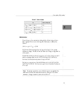
Table 1: Gain Values
If..
Use a Gain of..
V
max
+ offset > 1.28 V
0.5
0.64 V < V
max
+ offset
≤
1.28 V
1
0.32 V < V
max
+ offset
≤
0.64 V
2
V
max
+ offset
≤
0.32 V
4
Summary of Contents for DT3152-LS
Page 1: ...MACH Series UM 16481 F DT3152 LS User s Manual ...
Page 4: ......
Page 16: ...About this Manual xvi ...
Page 17: ...1 1 Overview Features 2 Supported Software 4 Accessories 6 ...
Page 142: ...Chapter 4 126 ...
Page 153: ...137 A Specifications ...
Page 156: ...Appendix A 140 ...
Page 162: ...Appendix B 146 ...
Page 192: ...Appendix C 176 ...
Page 193: ...177 D Asynchronous Reset Cameras ...
Page 196: ...Appendix D 180 ...
Page 210: ......
Page 214: ......

