


3-3
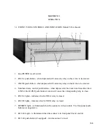
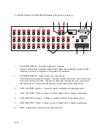
7. PROTECT CIRCUIT - Connect to same terminals on other scanners. Provides
protection for standards in a multiple scanner system. See Section 3.9 for details.
8. INTERFACE BUS - IEEE-488 bus connector used to connect scanner to controller.
9. FUSE - Use 0.25 amp, Type 3AG slow blow.
10. AC LINE INPUT - AC Power connector IEC Type with offset pin connected to chassis.
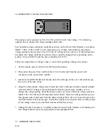
3.3 FRONT PANEL OPERATION
The scanner must be in local mode (LOCAL light on) to operate from the front panel. If
the REMOTE light is on, press the LOCAL push-button or turn power off and then on to
reset.
To connect one of the channel inputs to LINE A proceed as follows:
a. Press and hold down the LINE A push-button. This will cause any previously closed
relay on the A LINE to be cleared.
b. Press the numbered push-button corresponding to the input to be connected. This
will cause the relay to actuate connecting the input line to the A output and also turn
on the appropriate light.
c. To actuate a LINE B relay repeat the above process except hold down the LINE B
push-button.
NOTE: The push-buttons can be depressed in either order and the end result will be the same;
that is, any previously closed relay will be opened and the desired relay will be closed. The
important thing is that two push-buttons must be pressed for any relay to close.
Summary of Contents for 160A
Page 8: ...1 4 Blank Page ...
Page 10: ...2 2 Blank Page ...
Page 26: ...4 8 Blank Page ...
Page 30: ...5 4 ...
Page 41: ...6 11 ...
Page 43: ...6 13 ...
Page 47: ...6 17 ...


