


3-2
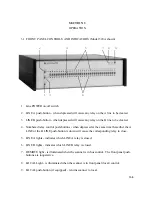
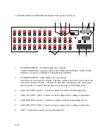
3.2 REAR PANEL CONNECTIONS (Model 320A option 2 is shown)
1.
SCANNER INPUTS - Terminal inputs, opt 2 (shown)
Connect red terminals to positive leads of units under test and negative leads to black
terminals. Numbers correspond to front panel relay numbers.
1. SCANNER INPUTS - Cable inputs, opt 1 (not shown)
Cable lines are in groups of four pairs. The relay numbers are shown on the color code
chart at the end of each cable. The lines in cable with red band are to be connected to
the unit positives. Connect the unit negatives to the lines with the black band.
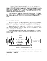
2. LINE A OUTPUT positive - Connect to positive terminal of measuring system.
3. LINE A OUTPUT COM - Connect to Line B output com for voltage comparisons.
4. LINE B OUTPUT positive - Connect to negative terminal of measuring system.
5. LINE B OUTPUT COM - Connect to Line A output com for voltage comparisons.
6. GND - Connected to chassis at relay isothermal box.
5V Max
to
DATA PROOF
SUNNYVALE, CA
U.S.A.
17
18
20
29
30
31
32
OUTPUT LINES
PROTECT
GP-IB BUS
~Line: 50-60Hz 27VA Max
~Fuse: (250V) 250mAT
GND COM A B
A
B
19
MODEL NO.
SERIAL NO.
320A Opt.2
725
HI
LOW
HI
LOW
~ 100V 115V / 127V
~ 220V 230V / 240V
100
220
120
240
3
4
5
6
7
8
9
10
11
12
13
14
15
16
21
22
23
24
25
26
27
28
INPUT LINES
1
2
6
7
8
5
3
2
4
9
1
10
!
All Lines 600V pk Max to
Summary of Contents for 160A
Page 8: ...1 4 Blank Page ...
Page 10: ...2 2 Blank Page ...
Page 26: ...4 8 Blank Page ...
Page 30: ...5 4 ...
Page 41: ...6 11 ...
Page 43: ...6 13 ...
Page 47: ...6 17 ...