Data Industrial Series 340 Btu transmitter Owner’s Manual
3
Se
ns
or
In
pu
t
Power Out
Signal
+
Signal
-
Shield
Te
m
p 2
Te
m
p 1
Mod
S/N 3
Input LED
Mattapoisett, MA
Red
Black
Shield
(if applicable)
Series 200
or
SDI
Po
w
er I
n
AC L/DC
+
AC C/DC
-
Ou
tp
ut
Pulse Out
-
Pulse Out
+
Output LED
Input LED
DC +
or
AC Load
DC -
or
AC Common
Earth
Ground
AC or DC
Power Supply
Temperature Sensor Installation
The location of the temperature sensors with regard to the flow
sensor is important to the accuracy of the energy calculation.
Temperature sensor
T1
must be located closest to the flow
sensor. A distance of 5 pipe diameters will give the greatest
accuracy. Always install the temperature sensor downstream
of the flow sensor.
Electrical Installation
All connections to the 340 are made to screw terminals on
removable headers.
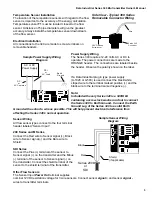
Power Supply Wiring
The Series 340 requires 12-24 Volts AC or DC to
operate. The power connections are made to the
ORANGE header. The connections are labeled beside
the header. Observe the polarity shown on the label.
If a Data Industrial plug in type power supply
(A-1026 or A-503) is used connect the black/white
striped wire to the terminal marked positive (+) and the
black wire to the terminal marked negative (-).
Note:
Included with every Series 340 is a 340IK kit
containing a screw, lock washer and nut to connect
the Series 340 to Earth Ground. Connect the Earth
Ground Lug of the Series 340 to a solid Earth
Ground with as short a wire as possible. This will help prevent electrical interference from
affecting the Series 340’s normal operation.
Sensor Wiring
All flow sensor types connect to the four terminal
header labeled “Sensor Input”.
200 Series and M Series
Connect the Red wire to Sensor signal (+), Black
wire to Sensor signal (-) and the Bare wire to
Shield.
SDI Series
Connect the Plus (+) terminal of the sensor to
Sensor signal (+) on the transmitter and the Minus
(-) terminal of the sensor to Sensor signal (-) on
the transmitter. Connect the shield terminal of the
sensor to the shield terminal of the transmitter.
Other Flow Sensors
The Sensor Input
Power Out
terminal supplies
nominal 12VDC excitation voltage for 3 wire sensors. Connect sensor
and sensor
signal -
wires to transmitter terminals.
Sample Sensor Wiring
Diagram
Side View - Typical 300 Series
Removable Connector Wiring
3/32” Flathead
Screwdriver
Series 300
Connector
Wire
Sample Power Supply Wiring
Diagram


