Configuring VME Option Boards
2-28
014–001867
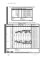
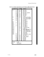
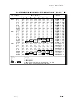
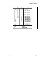
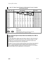
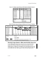
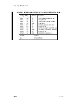
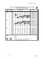
Table 2–18 Default Jumper Settings for VSC/3i Boards 0 Through 7 Variations
(Any Operating System)
Jumper Pins
Board Number
Function
0
1
2
3
4
5
6
7
JP16
In
Out
In
Out
In
Out
In
Out
Address bit A16
JP17
In
In
Out
Out
In
In
Out
Out
Address bit A17
JP18
In
In
In
In
Out
Out
Out
Out
Address bit A18
JP19
In
In
In
In
In
In
In
In
Address bit A19
JP20
In
In
In
In
In
In
In
In
Address bit A20
JP21
In
In
In
In
In
In
In
In
Address bit A21
JP22
Out
Out
Out
Out
Out
Out
Out
Out
Address bit A22
JP23
In
In
In
In
In
In
In
In
Address bit A23
JP24
Out
Out
Out
Out
Out
Out
Out
Out
Address bit A24
JP25
Out
Out
Out
Out
Out
Out
Out
Out
Address bit A25
JP26
In
In
In
In
In
In
In
In
Address bit A26
JP27
In
In
In
In
In
In
In
In
Address bit A27
JP28
In
In
In
In
In
In
In
In
Address bit A28
JP29
Out
Out
Out
Out
Out
Out
Out
Out
Address bit A29
JP30
Out
Out
Out
Out
Out
Out
Out
Out
Address bit A30
JP31
Out
Out
Out
Out
Out
Out
Out
Out
Address bit A31
Notation
Indicates
In
Jumper installed.
Out Jumper
removed.
In
or
Out
Jumpers that you must install (In) or remove (Out) in the field;
all other jumpers are factory-configured, as indicated.
Changing the Synchronous Electrical Interface for VSC/3i
Channels
You can independently configure each full–duplex channel on a VSC/3i controller to
support RS–232–C, RS–449, RS–530, V.35, or X.21 synchronous devices. RS–530,
RS–449, and X.21 devices share the same electrical interface; the VSC/3i also
provides separate V.35 and RS–232–C communication.
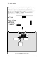
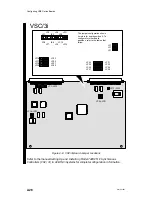
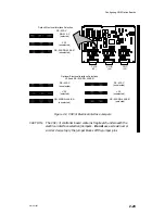
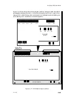
As shown in Figure 2–9, each connector has three rows of 20 jumper pins associated
with it. You can change the electrical interface between each channel and the
Motorola 68302 Integrated Multiprotocol Processor by placing two 10–pin headers
(or jumper blocks) across the appropriate row of jumper pins.
Summary of Contents for AViiON 5000 Series
Page 2: ......
Page 6: ......
Page 12: ...Preface x 014 001867 ...
Page 86: ...Configuring VME Option Boards 2 52 014 001867 ...
Page 144: ...Connecting External Devices to VME Option Boards 4 44 014 001867 ...
Page 150: ...VME Backplane Connector Signals and Power Distribution A 6 014 001867 ...
Page 196: ...Assigning VME Data Bus and Interrupt Priorities E 10 014 001867 ...
Page 206: ......
Page 210: ...Appendix Title ...

