background image


26 

  Connection Sizes, Fluid Cooler (Dry Cooler) 

The information regarding 

Fluid Cooler (or often referred to as a “dry cooler”) connection sizes can be 

found in the individual Fluid Cooler User Manuals which should be referred to for more complete details. 

  Condensate Drain System 

Every  indoor  unit  has  a 

3/4”  (19  mm)  copper  stub  provided  for  condensate  removal.  A  union  (field 

provided) is recommended at the field connection which will permit easy disconnection from the unit for 
cleaning. 

A trap should be built into the drain line to prevent air from backing up into the unit. Drain lines should 
be pitched downward not less than 

1/4” (6.35 mm) for each ten (10) feet (3.1 m) of horizontal run. The 

following are recommendation for condensate drain systems: 

1. 

Do not reduce the size of the condensate drain line.


2.  The condensate drain piping must be run to an unrestricted waste line and must be protected 

from freezing. 

3.  In high humidity conditions it is recommended to insulate the condensate drain line to prevent 

condensation forming on the exterior of the piping. 

4.  It is recommended that a union (field supplied) be installed at the 

3/4” (19 mm) FPT connection 

to permit easy disassembly of the condensate drain piping from the unit for cleaning. 

5. 

Drain lines should be pitched downward not less than 1/4” (6.35 mm) for each ten (10) feet (3.1 
M) of horizontal run. 

6.  Where local codes permit, PVC pipe may be used. 

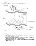
7.  Ceiling  units  with  an  optional  vertical 

discharge  have  a  5”  (127  mm)  plenum  below  the 

evaporator drain pan. The plenum has knockouts that allow routing of the field supplied and 
installed condensate drain piping system. The drain line can be routed out either side of these 
units. 

Some applications have no convenient means of allowing a gravity drain. When required, an optional 
condensate  pump  for  a  Mini  unit  can  be  used.  Condensate  pumps  can  be  internally  mounted  and 
powered  from  the  unit  or  externally  mounted  and  powered  from  separate  power  source  which  are 
shipped loose. 

Condensate  pumps  shipped  loose  (or  field  provided)  typically  require  a  dedicated  110-volt  power 
source. Field pipe connections must be made to the pump discharge connection. A check valve must 
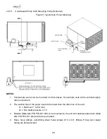
be installed to prevent short cycling. See condensate pump electrical requirements in 

3.11 Condensate 

Pumps

. 

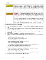
Do not expose drain line to freezing temperatures. Drain line may contain boiling water therefore use 
copper or other suitable material. Drain line must comply with local building codes. It is recommended 
to install water leak detection equipment whenever possible. 


Summary of Contents for DAMA-01

Page 1: ......

Page 2: ...d in areas such as HVAC electrical plumbing and electronics as applicable WARNING Service performed by unauthorized or unqualified technicians may void manufacturers warranties and could result in pro...

Page 3: ...Condensing Units 18 Piping 18 Split Air Cooled Unit Piping 19 Discharge Lines 19 Liquid Lines 21 Suction Lines 21 Recommended Line Sizing 21 Hot Gas Lines 22 Liquid Lines 22 Suction Lines 22 Connecti...

Page 4: ...tion 45 Third Stage Evacuation 45 Final Evacuation Stage 46 General Pre Charging Guidelines 46 Voltage Phase Check 47 Evaporator Power Phase Check 47 Fixed Speed Scroll Compressor Phase Check 47 Heat...

Page 5: ...midifier Canisters 69 Refrigerant Filter Drier 69 EC Plenum Plug Fans 70 Electronically Commutated Motors 70 EC Motor Testing 71 MAINTENANCE INSPECTION CHECKLIST 72 Frequently Asked Questions FAQ 75 E...

Page 6: ...le 11 Liquid Line Multiplier 48 Table 12 Liquid Line Multiplier for R 410A at Various Line Lengths 49 Table 13 Liquid Line Multiplier for R 407C at Various Line Lengths 49 Table 14 DAMA Starting Charg...

Page 7: ...space within the operating envelope ASHRAE recommends for data centers Operating outside this envelope can alter the operating performance and decrease equipment reliability Return air to the unit mu...

Page 8: ...g located on the unit door for details NOTICE Any external damage or transportation damage on the freight carrier s forms Inspect the unit itself for internal damage A claim should be filed with the s...

Page 9: ...owing the condition of the unit and noting any discrepancies A copy of the log sheet should be sent to Data Aire Failure to perform the long term storage requirements may void the warranty CAUTION A c...

Page 10: ...sources Isolate from direct sun light Isolate from storage of hazardous materials and substances Refrigerant coils have been evacuated and pre charged with slight 1 to 3 PSIG 6 9 to 20 7 kPa nitrogen...

Page 11: ...raining that will enable them to perform their assigned tasks properly and safely It is essential that prior to performing any task on this equipment this individual shall have read and understood thi...

Page 12: ...et jacks If using a forklift or pallet jack make sure that the forks if adjustable are spread to the widest allowable distance that will fit under the skid Ensure the fork length is suitable for the u...

Page 13: ...of polyethylene is often used on walls and ceilings Walls and floors must also be painted with vapor seal paint All doors to the controlled space should be equipped with weather seals to prevent the...

Page 14: ...a safe distance from the unit The unit may be too tall to fit through a doorway while on the skid Measure the unit and doorway heights and refer to the installation plans to verify clearances prior to...

Page 15: ...nt that could sustain water damage should be avoided Horizontal Airflow Units All Mini ceiling units have horizontal airflow configuration with a 24 610 mm tall evaporator section Duct collars are fac...

Page 16: ...al vertical airflow is 28 5 724 mm high and are typically mounted over a standard 2 0 6 m x 4 1 2 m T bar ceiling grid supported by four 4 threaded rods The four 4 threaded support rods must be secure...

Page 17: ...ing installation The plenum typically mounts flush to the ceiling grid depending on available space above unit Figure 2 Unit with Vertical Plenum Mounting Method and Condenser Installation Air Cooled...

Page 18: ...All refrigerant piping should be is Type L Air Conditioning Refrigeration ACR hard drawn copper pipes Soft copper is unacceptable When brazing refrigerant lines an inert gas should be passed through...

Page 19: ...4 Split Air Cooled Unit Piping for a guideline on sizing refrigerant lines Standard piping practices must be used to ensure proper oil return and efficient operation The interconnecting lines to the r...

Page 20: ...o open the other end of the refrigerant line to allow the nitrogen to bleed off and not pressurize the piping Prevailing good refrigeration practices should be employed for piping support leak testing...

Page 21: ...sive liquid line pressure drop the air cooled condenser should be located above or at the same level as the evaporator Condenser installations more than 15 feet 4 6 m below the evaporator are not reco...

Page 22: ...2 5 3 8 3 8 1 2 1 2 3 3 8 3 8 1 2 1 2 4 3 8 1 2 1 2 1 2 5 3 8 1 2 1 2 1 2 Suction Lines Table 4 Suction Lines Inches OD Unit Tonna ge Equivalent Feet Meters 50 15 2 100 30 5 150 45 7 200 61 0 Horizon...

Page 23: ...r evaporator and remote condenser will not necessarily be the same as the field pipe size required In some cases these sizes will vary significantly Connection Sizes Water Glycol Cooled Units Table 6...

Page 24: ...e check valves are included internally in the evaporator section 4 Slope horizontal lines downward in the direction of the refrigerant flow 1 2 13 mm for every 10 feet 3 1 meters of line length 5 Inve...

Page 25: ...All piping to be per local and or state code 2 Condenser to be no more than 15 feet 4 6 M below evaporator 3 Slope horizontal lines downward in the direction of the refrigerant flow 1 2 13 mm for eve...

Page 26: ...assembly of the condensate drain piping from the unit for cleaning 5 Drain lines should be pitched downward not less than 1 4 6 35 mm for each ten 10 feet 3 1 M of horizontal run 6 Where local codes p...

Page 27: ...ater supply to the humidifier Improper installation application and service may result in water leakage from the unit Water leakage can result in severe property damage and loss of critical data cente...

Page 28: ...total static pressure is expected more vertical drop is required 2 Some applications have no convenient means of allowing a gravity drain In this case a condensate pump can be used These are shipped...

Page 29: ...r plenum 2 The suction line of the pump needs to be lower than the drain line of the unit L1 Minimum 1 25 4 mm L2 Fan static pressure x 1 5 3 Bracket Data Aire P N 550 021 006 to be mounted to the uni...

Page 30: ...on valves etc If the ambient temperature surrounding the piping system increases this may cause the contained refrigerant pressure to increase to an unacceptable level WARNING This increased pressure...

Page 31: ...drop of peripheral components Shutoff valves field provided should be installed within a few feet of the inlet and outlet connections of the evaporator to allow the unit to be isolated for service Dra...

Page 32: ...s a required component of a proper system installation The tank can be provided by Data Aire or by others 2 All Water Glycol field piping must be designed and installed in accordance with ASHRAE stand...

Page 33: ...r WARNING With any fluid connection there is risk of leakage Water leakage could result in property damage to mission critical equipment A water drain connection is required Units with optional steam...

Page 34: ...tment Contact Data Aire Service Department for details The commissioning includes pre startup inspections of installed components subsystems and systems and the execution of the verification and funct...

Page 35: ...nsed and qualified electrician Risk of electrical shock could result in injury or death Disconnect all remote electrical facility power prior to working on the unit All wiring must conform to local an...

Page 36: ...high voltage wiring Upon arrival of the unit inspect all wiring and electrical components for damage either visible or concealed before installation Use correctly sized copper wire only and verify tha...

Page 37: ...it breaker or fuse size required to protect the system Max Fuse or Max CKT BKR indicates the maximum breaker or fuse size and this information is used to size the appropriate fuses or a Heating Air Co...

Page 38: ...indoor evaporator to the electrical control box of the remote heat exchanger require heavier gauge wire and a special Parts order for a low holding current relay is required Consult Data Aire Parts de...

Page 39: ...umper clip prior to installing the field wires Mini dap4 Controller The Mini ceiling unit is furnished with programmable thermostat but can be upgraded to a microprocessor based Mini dap4 or Expanded...

Page 40: ...pump power requirements before connecting power Condensate pumps are available in other voltages When a condensate pump needs to be mounted outside of the cabinet of the unit mount the provided pump t...

Page 41: ...l Simply slide the manual switches to energize the fan compressor s humidification reheat and other functions as applicable Some DAM may have a special Electronically Commutated EC plug fan motor and...

Page 42: ...ing diagram in the evaporator will indicate field interface terminals to the secondary heat exchanger The internal wiring of the secondary heat exchanger is found on a separate diagram which can be fo...

Page 43: ...410A pressure High pressure recovery machine suitable for R 410A pressure High pressure recovery tank suitable for R 410A pressure Ref DOT 4BA400 or ABW400 Triple Evacuation and Dehydration Procedure...

Page 44: ...l tool Two Stage Vacuum Pump s NOTICE Two pumps will speed up the procedure One 1 vacuum pump located normally outside at the condenser and one 1 vacuum pump is located indoors at the evaporator unit...

Page 45: ...the nitrogen bottle regulator to the manifold gauges vacuum port and carefully break the vacuum with clean dry nitrogen Slowly raise the pressure to approximately 5 PSIG 35 kPa without contaminating t...

Page 46: ...before the unit is put back on the pump for dehydration 8 After the system has been satisfactorily evacuated the evacuation equipment can be removed and the system can be charged with refrigerant 9 Ma...

Page 47: ...fset the cooling load Suction pressure should be equal to 33 F 0 56 C saturated temperature or greater See further instructions for the following options Section 5 8 2 Air Cooled Split System Charging...

Page 48: ...s and Maintenance Manual for additional information regarding this type of heat exchanger DARC Heat Exchangers Phase Check See the DARC Air Cooled Condensers Installation Operations and Maintenance Ma...

Page 49: ...0 407 20 33 40 65 60 98 81 31 Component Functional Test Critical components can be functionally verified by using the manual mode of the Mini dap4 See Mini dap4 User Manual for details regarding how...

Page 50: ...sphere per the latest edition of ASHRAE Standard 15 and or any local building fire or mechanical codes This applies to all units with either shell and tube condensers or high pressure relief valve opt...

Page 51: ...AMA Starting Charge R 407C Weight of Refrigerant in Evaporator and Condenser Evaporator Model Condenser Model Starting Charge lbs DAMA 01XX GHRC 011XX or DARC 03XX GHRC 018XX or DARC 05XX Option GHRC...

Page 52: ...al for details During manual control all automatic control is disabled but the system safety switches will remain functional Charging the Fixed Speed Compressor Charging requires the unit the unit ope...

Page 53: ...he correct refrigerant charge Other parameters such as superheat suction pressure head pressure subcooling and ambient temperature are also important factors A system charged to a clear sight glass is...

Page 54: ...r Package NOTICE Prior to refrigerant charging the proper tools and or equipment must be available and the system vacuum and moisture removal procedure must have been carried out Refer to Section 5 2...

Page 55: ...warmer weather The receiver should be sized so it is at 80 to 82 of capacity while containing the entire system charge Another aspect of receivers is that they contain both liquid and gaseous refriger...

Page 56: ...ition in the receiver See section 2 27 Refrigerant Piping Protection for additional information regarding piping and receiver over pressure protection Receiver Installation Be sure the receiver capaci...

Page 57: ...e charging line to the refrigerant tank and set for liquid feed Open the refrigerant tank valve and purge the line Use a liquid charging adapter to break the vacuum with 90 PSIG 621 kPa of liquid refr...

Page 58: ...e to increase Once you reach the pressure value shown below enable the condenser fans and continue to charge each circuit until it reaches the value shown Table 18 Discharge Head Pressure Refrigerant...

Page 59: ...Table 20 Packaged Units with Receivers Acceptable parameters range for water glycol packaged units with receivers with return air temperature of 65 F 18 3 C to 85 F 29 4 C and entering water glycol te...

Page 60: ...lower the superheat 3 Turn the adjusting stem clockwise to increase the superheat NOTICE Make no more than one turn of the stem at a time As long as thirty minutes 30 may be required for the system to...

Page 61: ...or during the OFF cycle The Liquid Line Solenoid Valve LLVS is a direct acting NC normally closed i e closed when deenergized solenoid operated valve The advantage is the valve is closed when the syst...

Page 62: ...ich should be referred to for more complete details regarding remote heat exchangers Brazed Plate Fin Condensers Data Aire water cooled units use brazed plate condensers as a standard Brazed plate con...

Page 63: ...d be kept smaller than 0 8 mm and is recommended to fit a 40 to 70 mesh strainer Regular maintenance of this unit is required to ensure continued performance 6 2 3 3 Dissolved products Under certain c...

Page 64: ...r testing and maintenance of inhibitors Commercial ethylene glycol when pure is generally less corrosive to the common metals of construction than water itself It will however assume the corrosivity o...

Page 65: ...9 2 1 2 63 5 2 625 66 7 0 248 0 939 24 8 93 9 3 76 2 3 125 79 4 0 354 1 34 35 4 134 Freezing Point of Aqueous Solutions Table 25 Freezing Point of Aqueous Solutions Ethylene Glycol by Volume Freezing...

Page 66: ...ted formula ethylene glycol and propylene glycol are supplied with corrosion inhibitors and do not contain a silicone anti leak formula Commercial ethylene glycol and propylene glycol when pure are ge...

Page 67: ...arding functions features programming and troubleshooting NOTICE The Mini dap4 microprocessor controller has an entire manual dedicated to its use and operation This manual must be referenced to compl...

Page 68: ...the air filter pressure differential pressure switch for proper adjustment temporarily cover approximately 75 of the return air opening using heavy cardboard or similar material The alarm should energ...

Page 69: ...the burning debris can create smoke or an unpleasant odor To help avoid a problem periodic cleaning is recommended Humidifier Optional If the unit is provided with an optional self contained micropro...

Page 70: ...ically Commutated Motors WARNING The plug fan modules are powered by high voltage input line power i e 208 230V 3PH 60HZ or 460V 3PH 60HZ Do not carry out any work on electrically live parts Even afte...

Page 71: ...e unit controller Expanded dap4 has a time delay before the No Airflow alarm is energized It is adjustable from 5 to 180 seconds in 5 second increments On site where a voltage problem is known to exis...

Page 72: ...ns Inspect contactor operation Check operation sequence Controls Type Thermostat Mini dap4 Expanded dap4 Check unit control operation Check operation of the following High water alarm Pressure differe...

Page 73: ...secure Check capillary lines Condensate Pan and Pump if equipped Check for leaks Check for debris Inspect check float operation Check pump operation Condensers Water Cooled Check for water glycol lea...

Page 74: ...an blade s Check wiring Inspect piping for leaks Glycol Pump Monthly if applicable Glycol leaks pump area Pump operation Auto air vent clean of mineral deposits Glycol Pump Quarterly if applicable Rec...

Page 75: ...the maximum protective device Question 4 What is the input voltage tolerance Answer In general it is 10 but refer to Electrical Section for more details Question 5 Will all units operate at 50 or 60...

Page 76: ...ated on the unit serial name plate label Question 15 What is the SCCR rating for the unit Answer SCCR is short circuit current rating Unless specified the SCCR rating is 10 kA root mean square symmetr...

Page 77: ...umidifiers can be adjusted within the range minimum to 100 Factory setting is 60 of capacity Question 5 Is an air vent valve required in the piping when an expansion tank is used Answer Yes air vents...

Page 78: ...strainer 12 Low pressure drop across the valve a Same as 11 above b Undersized distributor nozzle or circuits c Low condensing temperature 1 Oversized TXV 2 TXV seat leak 3 Low superheat adjustment 4...

Page 79: ...vice dataaire com Engineering dataaire com Sales dataaire com Fax 714 921 6010 Main 714 921 6011 Engineering 714 921 6022 Parts Sales Web Site www dataaire com Job Unit Information Data Aire Job Numbe...

Page 80: ...Power Off 75 Equipment Runtimes 74 Evacuation 43 49 54 Expanded dap4 67 71 72 F Flooded system 55 57 Fluid cooler 62 Frequent Asked Questions 75 Full Load Amps FLA 75 Fuses 69 G Glycol System 37 62 Gr...

Page 81: ...e Condenser Condensing Unit 24 25 Remote EPO Switch 76 Remote Graphic Touch Display 67 Remote Heat Exchanger 39 62 67 Remote Sensor 40 Remote Shutdown 39 75 Rigging 14 S Safety Relief Devices 56 Short...

Page 82: ...MiniCeiling_IOM 10 2022...

Reviews: