20
NOTICE:
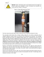
Picture of the check valve is only intended to show an example of a
common check valve installation. It may not represent your specific unit,
check valve size, location or orientation.
Figure 3 Typical Discharge Check Valve
The check valve will prevent flow from the condenser to the compressor during the off cycle.
The evaporator section ships with a nitrogen holding charge. Do not vent the evaporator until all
refrigerant piping is in place, ready for connection to the evaporator and condenser. The discharge,
suction and liquid lines need to be refrigerant grade copper and in accordance with local code. All
refrigeration piping should be installed with high temperature brazed joints. When brazing, a supply of
nitrogen gas needs to be fed through the refrigerant lines. Be sure to open the other end of the
refrigerant line to allow the nitrogen to bleed off and not pressurize the piping. Prevailing good
refrigeration practices should be employed for piping support, leak testing, dehydration and charging
the refrigerant circuits. During the installation, the lines should be capped off and filled with dry nitrogen
at the end of each day’s work or until the system is completed and sealed.
Data Aire recommends a silver/phosphorus/copper alloy with 5 to 15% silver be used to braze the
refrigerant line sets to the indoor and outdoor units. Nitrogen needs to be flowing through the lines to
eliminate carbon deposit buildup on the inside of the joints. Carbon could contaminate the refrigerant
and restrict the metering device.
Piping
must be supported within 18” (457 mm) of the inlet and outlet connections external to the unit.
Internal to the unit, the inlet connection is located on the top header of all units. The discharge outlet is
located at the bottom of the header.
Summary of Contents for DAMA-01
Page 1: ......
Page 82: ...MiniCeiling_IOM 10 2022...


