background image

7

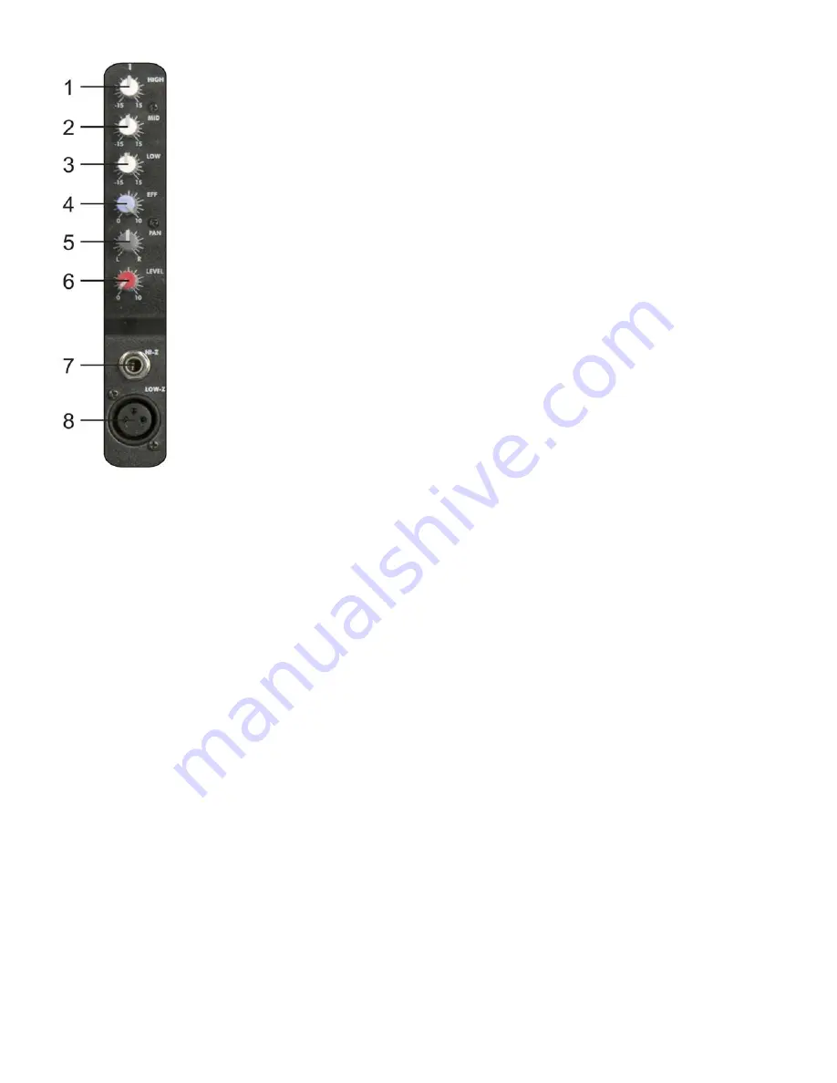
1 / 2 / 3. Equalizer SECTION (HI / MID / LOW)

The mixer’s Equalizer section allows shaping of the incoming audio signal. All mono
input channels are fitted with 3-band EQ. The upper (

1

) and lower (

3

) shelving

controls have their frequencies fixed at 12 Khz and 80 Hz respectively. The Mid range
control (

2

) has a peaking response frequency at 2.5 Khz. All 3 bands have up to 15

dB cut and boost, with a centre detent for “OFF”. Turning the Equalizer level control to
the right amplifies the frequency range, turning to the left attenuates the signal. Minor
changes to the Equalizer control usually produce the best results. Try to avoid
excessive enhancement of the MID band.

4 EFF

The EFF control allows you to change the EFF Level to the FX Mix.
The range is from 0 – 10

Using the EFF control lets you route the corresponding input signal to the integrated
digital effects unit EFF at variable levels. In this way assigning special effects to
musical instruments or vocals is fairly simple. When establishing an effect-mix, it’s
advisable to start with the EFF-control set to the center position. You can further
increase or reduce the effect’s intensity, depending on your personal preferences.
Please make sure to carefully monitor the PEAK LED in the EFF channel during a
performance.

5. PAN

By using the PAN control you can change the input signal’s position within the stereo
image. When the PAN control is set to center position, the audio signal is equal for
both the left and right buss.

6. LEVEL

The channel level control allows you to adjust the signal level of the respective input
channel in the mix.

7. LINE

Electronically balanced inputs for connecting a keyboard, CD player, mixer, etc. You
can connect balanced or unbalanced signal sources to the Line input. Do not connect
signal devices to a channel’s MIC and LINE input at the same time. This will cause
mutual interference, which results in level reduction.

Note: When connecting signal sources, please make sure that the
corresponding channel faders and the master faders are at their minimum
settings. Otherwise unpleasant plug-in noise can occur.

8. MIC

Electronically balanced XLR-type inputs for connecting low-impedance microphones.
The input provides extremely low noise and low hum signal processing. When
connecting a microphone make sure that the pin assignment is correct. Always make
sure to read the manual of the microphone you want to connect. The XLR-inputs are
not suitable for connecting an additional mixing console, FX-unit, etc. You have to use
the LINE-inputs, when connecting this kind of equipment.

Summary of Contents for Power Jig 6

Page 1: ...Power Jig 6 ORDERCODE D2230...

Page 2: ...AP Audio for more excellent audio products We design and manufacture professional audio equipment for the entertainment industry New products are being launched regularly We work hard to keep you our...

Page 3: ...DAP Audio Power Jig 6 Product Guide Warning Safety instructions Operating Determinations Description Features Overview Frontside Backside Installation Set Up and Operation Set Up Connection Cables Mai...

Page 4: ...ith the mains with particular caution Never remove warning or informative labels from the unit Never use anything to cover the ground contact Never leave any cables lying around Do not insert objects...

Page 5: ...sing the INPUT control To emphasize a frequency range you don t necessarily have to move its respective sliding control upward try lowering surrounding frequency ranges instead This way you avoid caus...

Page 6: ...wermixer from Dap Audio 6 mono Hi Z 1 4 Jack inputs 6 Low Z XLR Inputs High quality sealed potentiometer Rugged design power supply ensures superior signal integrity 2 groups Output Stereo Master Ampl...

Page 7: ...put mono 9 Left 7 band Graphic equalizer 10 Right 7 band Graphic equalizer 11 Equalizer LEDs 12 Tape range 0 10 scale 13 Master range 0 10 scale 14 Effect Volume range 0 10 scale 15 Depth range 0 10 s...

Page 8: ...Connector Main Fuse T5A L 250V 30 Power On Off Installation Remove all packing materials from the Power Jig 6 Check that all foam and plastic padding is removed Connect all cables Always disconnect fr...

Page 9: ...ease make sure to carefully monitor the PEAK LED in the EFF channel during a performance 5 PAN By using the PAN control you can change the input signal s position within the stereo image When the PAN...

Page 10: ...ft and Right 12 TAPE You can adjust the input volume with this knob 13 MASTER You can adjust the master volume with this knob 14 EFF VOLUME You can adjust the EFF volume with this knob 15 DEPTH You ca...

Page 11: ...e ground 23 POWER LED The blue Power LED lights when the PowerMix is turned on If after switching the PowerMix on the LED does not light make sure that the mains plug is plugged in correctly If the LE...

Page 12: ...tion Before plugging the unit in always make sure that the power supply matches the product specification voltage Do not attempt to operate a 120V specification product on 230V power or vice versa Set...

Page 13: ...always to your advantage Periodically check that your cables are in good condition that they are correctly wired and that all their contacts are perfectly efficient a great number of problems faulty...

Page 14: ...ly dry before linking equipment or supplying electric power Troubleshooting DAP Audio Power Jig 6 This troubleshooting guide is meant to help solve simple problems If a problem occurs carry out the st...

Page 15: ...Outputs 1 Headphones 1 4 jack 1 Effect Out 1 4 jack Rec Out RCA Frequency range Microphone 10 Hz 60 kHz 3 dB Mono 10 Hz 60 kHz 3 dB Stereo 10 Hz 55 kHz 3 dB Distortion 0 01 S N ratio 112 dB Tone cont...

Page 16: ...2005 DapAudio...

Reviews: