background image

5

Fig. 2

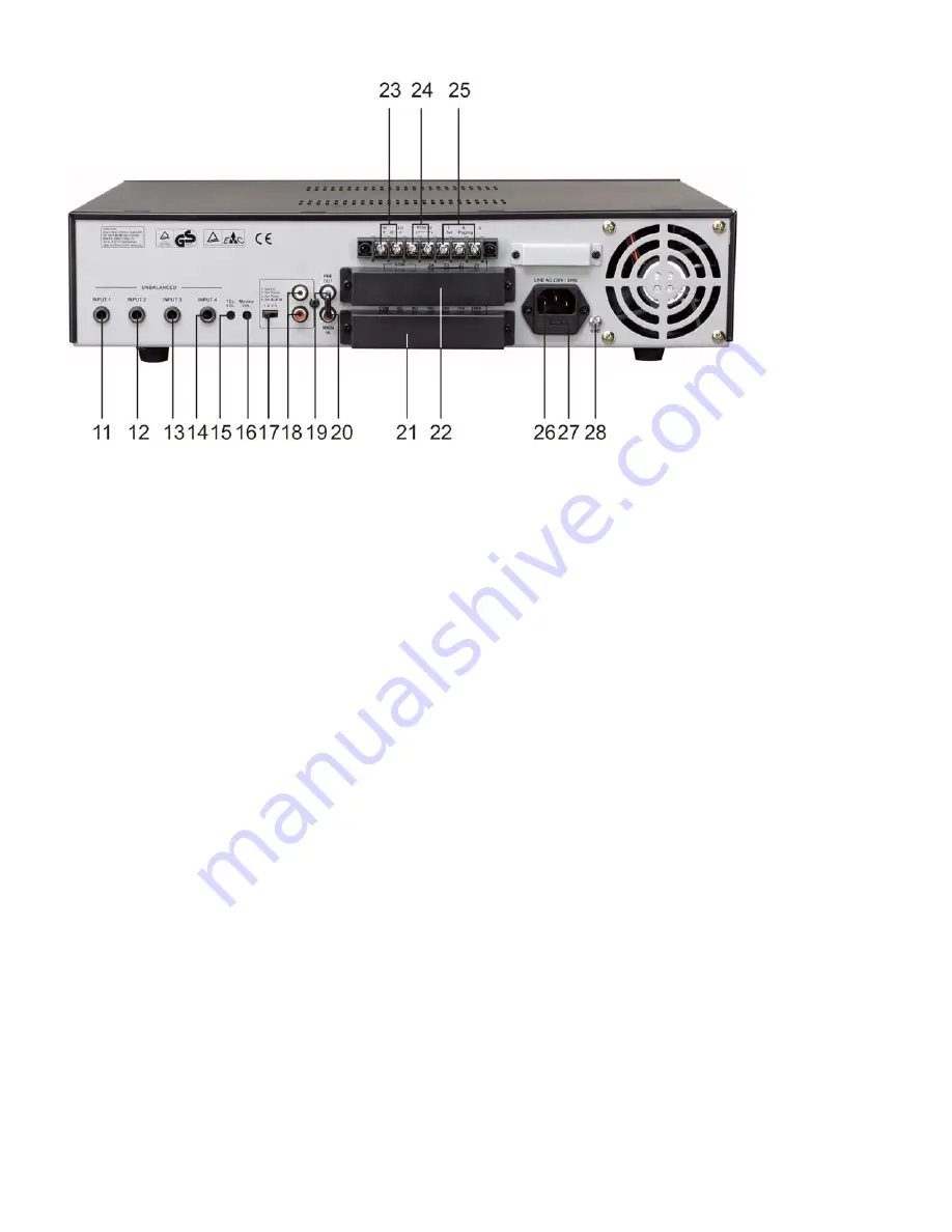
11-14)

 INPUT 1-4: These four unbalanced combination jack 6.3mm inputs, dynamic microphone

(30-600

)or a high level sound source (e.g. AM/FM tuner, cassette desk, CD player, etc.).

INPUT 1 has a "Voice Priority" function that mutes all the other inputs as soon as a message is
transmitted with a microphone; it is possible to exclude this function by calling a qualified SERVICE
CENTER.

15)

 Tel. Paging input level control

This control lets you set the volume of the sound source, which is connected to the "Tel. Paging"(

25

)

terminals. Turning the control clockwise increases the volume of the corresponding source. We
recommend to leave the control of the momentarily not used inputs at their minimal setting "0".

16)

 Music signal monitor output level control

The control lets you individually set the volume of the sound source output that is connected to the
"MONITOR OUTPUT 1W/8

 " (

23

) terminals. Turning the controls clockwise, increases the volume of

the corresponding source.

17)

 Input sensitivity switch (AUX IN)

Setting this switch to the "CD" position, the "AUX IN" input is suitable for connecting to a CD player
signal output.
By setting this switch to the "TUNER" position, the "AUX IN" input is suitable for connecting to an AM/FM
radio. By setting the switch to the "TAPE" position, the "AUX IN" input is suitable for connecting to a
cassette player.

18)

 "AUX IN" inputs

The "R" and "L" sockets permit the input of the right (

R

) and left (

L

) channels of an audio source with a

high-level output signal, such as an AM/FM tuner, a cassette deck, a CD player, etc. Use input
sensitivity switch (

17

).

19)

 "PREAMP OUT" socket

This output sends the sum signal of all the connected sources and can be used to feed an external
power amplifier, a signal processor (e.g. an equalizer), or any other external device. The unbalanced
signal is affected by the individual input controls. Before using the PREAMP OUT you have to remove
the bridging-strip between this socket and the "MAIN IN" socket (

20

) and preamp out terminal sockets.

20)

 "MAIN IN" socket

After removing the bridging-strip between the "PRE OUT" and the "MAIN IN" sockets you can include
an external signal processor (e.g. an equalizer) in the audio-chain between the pre-amplifier and the
power output stage of the power amplifier. This opportunity provides a proper solution whenever shaping
or improving the audio signal is necessary (adjusting delay times, equalizing, eliminating unwanted
feedback from the mic to the loudspeakers, etc.). The input is unbalanced.

Summary of Contents for PA180

Page 1: ...PA180 ORDERCODE D6112...

Page 2: ...Audio for more excellent audio products We design and manufacture professional sound equipment for the entertainment industry New products are being launched regularly We work hard to keep you our cus...

Page 3: ...Dap Audio PA180 Product Guide Warning Safety instructions Operating Determinations Description Features Frontside Backside Installation Set Up and Operation Set Up Example 1 Connection Cables Maintena...

Page 4: ...ver remove warning or informative labels from the unit Do not open the device and do not modify the device Do not insert objects into air vents Do not connect this device to a dimmerpack Do not switch...

Page 5: ...ct mains power supply immediately Have a qualified engineer inspect for safety before operating If the device has been exposed to drastic temperature fluctuation e g after transportation do not switch...

Page 6: ...ut Level meter For proper operation of the amplifier keep the correct volume setting 2 AC Power On Off 3 Zone paging selection switch Speaker lines Z1 Z4 of each zone can be connected disconnected ind...

Page 7: ...witch to the TUNER position the AUX IN input is suitable for connecting to an AM FM radio By setting the switch to the TAPE position the AUX IN input is suitable for connecting to a cassette player 18...

Page 8: ...6 21 Output terminals These 5 terminals allow connecting speakers...

Page 9: ...put of 1 watt Only the mixed audio signal coming from AUX IN is included in the output signal In addition the output signal is controlled only by the volume control of INPUT 5 music level control 10 2...

Page 10: ...r back onto the amplifier Fig 3 Installation PA180 Installation Remove all packing materials Check that all foam and plastic padding has been removed If you want to use the amplifier in a 19 Rack you...

Page 11: ...25V 70V 100V Connection 1 Each speaker must be equipped with a line transformer with an input voltage equal of the line voltage used 2 The sum of the power capacities of the speakers must not exceed...

Page 12: ...and will accept the line level output of most devices The correct input depends on 2 factors 1 whether the input signals are balanced or unbalanced and 2 whether the signal source floats or has ground...

Page 13: ...11 Set Up Example 1 Fig 4...

Page 14: ...always to your advantage Periodically check that your cables are in good condition that they are correctly wired and that all their contacts are perfectly efficient a great number of problems faulty...

Page 15: ...t or supplying electric power Troubleshooting DAP Audio PA180 This troubleshooting guide is meant to help solve simple problems If a problem occurs carry out the steps below in sequence until a soluti...

Page 16: ...the volume turned to full 2 Were the speakers connected correctly 3 Were the wires of the speaker connected correctly 4 Is the impedance of the speakers correct 5 Is the speaker good 1 Turn down the...

Page 17: ...25 20dB 50 100mV 47K bal unbal AUX IN stereo RCA jack unbalanced CD 5dB 570mV 80K TUNER 10dB 300mV 56K ATPE 15dB 200mV 20K AUX1 20dB 100mV 20K MAIN IN mono R A jack 0dB 1V 10K unbalanced Additional o...

Page 18: ...2006 DapAudio...

Reviews: